Epicyclic Gearbox: Components, Working Principle, Advantages, Disadvantages, and Applications [PDF]
Epicyclic Gearbox is also known as Planetary Gearbox or Planetary Gear Train or Epicyclic Gear Train. It is used as a transmission system to get various speed ratios in forward as well as in reverse directions.
Introduction of Transmission Systems:
As you know that they are two types of Transmission systems. One is Manual Transmission System and the other is an Automatic Transmission System each of these Transmission systems is categorized as follows.
Manual Transmission System:
The Transmission systems which are under Manual Transmission System are
Automatic Transmission System:
The Transmission systems which are under the Automatic Transmission System are
- Epicyclic Gearbox
- Torque Converter
- Overdrive in Automobile
So, in this article, we can discuss in detail about Epicyclic Gearbox also called Planetary Gearbox w.r.t. various cases and during working, various observations are seen and all these things will be discussed here.
Let's dive into the article.
Epicyclic Gearbox in Detailed
Epicyclic Gearbox plays a vital role in the case of the Automatic Transmission System. There is no need for the application of pressure on the clutch pedal rather just apply the pressure on the accelerator. From this Planetary Gearbox, we can achieve different speed ratios w.r.t. the components present in it.
We can see the various Cases and Observations noticed during the running of the Epicyclic Gearbox.
Components of Epicyclic Gearbox:
The Epicyclic Gearbox consists of four components.
- Sun Gear
- Planet Gears
- Ring Gear
- Planet Carrier.
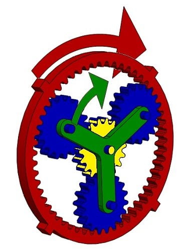
Sun Gear - Yellow Color
Planet Gears - Blue Color
Ring Gear - Red Color
Planet Carrier - Green Color
Sun Gear:
The shaft attached to the Sun Gear acts as an input of power transmission from the Engine. It is located at the center of the Gearbox and was in mesh with the Planet Gears. More than one sun gear is also attached to achieve different outputs.
Planet Gears:
The Planet Gears can rotate around their axis and also under the axis of the Sun Gear and Ring Gear.
The Planet Gears are under constant mesh with Sun Gear and the Ring Gear for transmitting the torque.
Ring Gear:
It is the outermost Gear which was in the form of a ring whose inner side has angular cut teeth such that they will be in mesh with the outer teeth of the planet gears.
When the Ring Gear is under motion, it will achieve higher speeds than others which are analyzed in detail in this article.
Planet Carrier:
Planet Carrier is used for the support of planet gears which are in mesh with Sun Gear and the Ring gear.
It is a carrier that is attached to the axis of the Planet Gears and the carrier is responsible for the final transmission.
Now let's understand how these parts are responsible for achieving higher speeds in the Gearbox.
Working Principle of Epicyclic Gear Train:
In the running conditions of the Epicyclic Gearbox, it is observed that the speed of the output shaft will be sometimes slow, sometimes fast and sometimes it can even reverse its direction also.
But do you know how the change in speeds is taking place?
I have taken 3 cases to understand the concept of the Epicyclic Gearbox in detail.
Case 1: Ring Gear is Stationary and the Sun gear is under rotation.
Case 2: Sun Gear is Stationary and the Ring gear is under rotation.
Case 3: Planet Carrier is Stationary and the Sun gear is under rotation.
But before analyzing all the cases, you need to have a piece of basic knowledge on how Gear mesh with each other?
How does Gear mesh with another Gear?
When two gears are rotating under the mesh, then they should have the same speed at the interface i.e. The speed of a Gear A should be equal to the speed of Gear B.
i.e. Velocity of Gear A = Velocity of Gear B.
If the speed of these two Gears A and B are not equal, then they will penetrate each other which results in wear and tear of the tooth.
Make sure that the above condition is to be satisfied i.e. Vel of A = Vel of B.
Now let's analyze the Planetary Gearbox with all the 3 cases.
Case 1:Ring Gear is Stationary and Sun gear is under rotation
As ring gear is stationary, we need to focus only on the other parts of the epicyclic gearbox i.e. Sun Gear, Planet Gear, and the Planet Carrier.
As soon as the Ring Gear is stationary, the Sun Gear starts rotating which is taking the power from the clutch shaft. Here, the shaft which is attached to the Sun Gear is the Input Shaft to the transmission system.
The Planet Gears which are meshed with Sun Gear and the Ring Gear revolve around them.
Consider two points A and B when the Planet Gear mesh with the Sun Gear as shown in the figure.
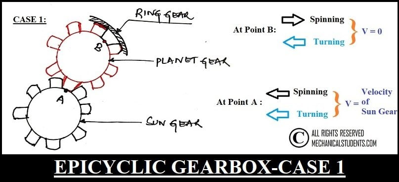
At point A, the Planet Gear should have a certain speed and at Point B, the speed of Planet Gear is zero because the ring gear is stationary.
The only way to satisfy these conditions is the Planet gear should have to "Spin as well as Turn".
The spinning will produce velocities in the opposite direction at the top and bottom points as shown in the figure whereas, turning produces unidirectional velocities.
At the top, the spinning and turning velocities are in the opposite direction. So, the velocity at point B is zero whereas, at the bottom, they will be added up because the spinning velocity and turning velocity can move only in one direction.
As the carrier is attached to the planet gear, it will turn along with the planet gears. Thereby, we can get a lesser speed.
The speed of the Planetary Gearbox is calculated by the below formula i.e.
V = (radius) of Sun Gear * ω(angular velocity)
Observations of Case 1:
- Ring Gear is fixed
- Sun Gear rotates in the CW direction
- Planet Gear rotates in the CCW direction.
Case 2:Sun Gear is Stationary and the Ring gear is under rotation
This is the opposite case as previous (Case 1) Therefore at point A, the speed is zero whereas, at point B, the speed is equal to the speed of the Ring Gear.
In this case, the planetary gear reverses its direction to satisfy the condition of speeds.
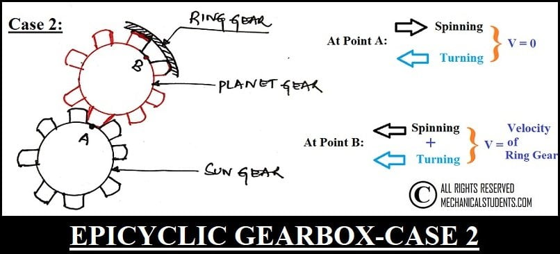
However, this case has one more difference I.e. The speed of point B will be higher than the speed of point A (compared to the previous case).
This is because the radius of the Ring gear is larger than the radius of the Sun gear.
This will make the Planet gear Spin and Turn at a higher speed and this will make the Planet Carrier rotate at a higher speed.
Thereby, the speed at the output shaft is very high compared to the previous case and is calculated by a formula.
V = (radius) of Ring gear * ω(angular velocity)
Note:
You can see in the formula that the radius of the gear is playing a vital role.
i.e. in Case 1, the Sun Gear is under motion. Therefore, the radius of Sun Gear is to be taken into consideration whereas in Case 2, the Ring Gear is under rotation. Therefore, the radius of the Ring Gear is to be taken into consideration.
Now, if you see the radius of the Ring Gear is more than the radius of the Sun Gear.
If you substitute these values in the given formula, then the speed of Ring Gear is more compared to the speed of Sun Gear because of its radius only.
Observations of Case 2:
- Sun Gear is Fixed
- Planet Gear rotates in the CW direction
- Ring Gear rotates in the CW direction
Case 3:Planet Carrier is Stationary and Sun gear is under rotation.
In this case, the planet gears are not allowed to turn, but they can spin and this spin will be opposite to the rotation of the Sun gear.
The Spinning Planet Gear will make the Ring Gear rotate in the opposite direction I.e. the direction of rotation of the Ring Gear will be opposite to that of Sun Gear. Thus we will get the reverse gear in this case.
Observations of Case 3:
- Planet Carrier is Fixed
- Sun Gear rotates in the CW direction
- Planet Gear rotates in the CCW direction
- Ring Gear rotates in CCW direction
This is a detailed explanation of Epicyclic Gearbox w.r.t various cases and observations.
Now Let's discuss the advantages of the Epicyclic Gear train.
Advantages of Epicyclic Gearbox:
The advantages of the Epicyclic Gear train are as follows.
- Epicyclic Gear trains exhibit higher gear ratios
- These are used in various automobiles and by this the effort of the driver will reduce and it increases comfort.
- These gear trains are also used in bicycles for controlling power during pedaling.
Disadvantages of Epicyclic Gearbox:
The disadvantages of the Epicyclic Gear train are as follows.
- The cost of manufacturing is high.
- Design complexity
- Constant lubrication is required
- high bearing loads
Applications of Epicyclic Gearbox:
The applications of the Epicyclic Gear train are as follows.
- They are used in running the armature of a wind turbine
- Used in various automobiles running under Automatic Transmission.
- It is also used in tractors and bicycles.
More Resources:
Sliding Mesh Gearbox
Constant Mesh Gearbox
Synchromesh Gearbox
External Links:
Design and Analysis of Epicyclic Gearbox
Media Credits:
Image 1: By AndrewDressel (talk) - I (AndrewDressel (talk)) created this work entirely by myself., CC BY-SA 3.0, https://en.wikipedia.org/w/index.php?curid=33814843
Image 2: By Laserlicht - Own work, CC0, https://commons.wikimedia.org/w/index.php?curid=49080501
Image 3,4: All Rights Reserved. Admin releases all rights but a photo credit would be appreciated if this image is used anywhere on any platform. Thank you!
Video: Learn Engineering