Synchromesh Gearbox: Construction, Working Principle, Advantages, Disadvantages, and Applications [PDF]
Synchromesh Gearbox is similar to the Constant Mesh Gearbox in which dog clutches in the Constant Mesh Gearbox are replaced by Synchromesh devices for smoother engagement of gears.
The gears on the main shaft are free to rotate w.r.t the main shaft whereas the gears on the layshaft are fixed I.e. there is no relative motion between them.
As you know that there are three types of Gearbox. They are
- Sliding Mesh Gearbox
- Constant Mesh Gearbox
- Synchromesh Gearbox
Who invented the synchromesh gearbox?
The Synchromesh gearbox was invented by Earl Avery Thompson in 1919 and was introduced in 1928 by Cadillac.
The need for Synchromesh Gearbox:
By the usage of Dog Clutches, the noise produced is low and the efficiency is high compared to the Sliding Mesh Gearbox.
The friction between the dog clutch and the associated gear will be less and due to this, there is a possibility of slip. To avoid this, the Synchronizers are used so that it can engage smoothly with the gears and there will be no slippage.
Is Double-DeClutching necessary?
Dog clutches in the constant mesh gearbox are replaced by Synchromesh devices or Synchronizers in Synchromesh Gearbox to avoid the necessity of double-declutching.
By the use of the Synchromesh Device, the parts which are to be engaged are first brought into frictional contact which equalizes their speed and after that, they may be engaged smoothly.
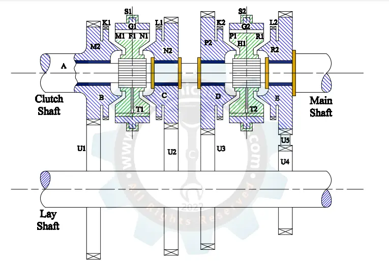
Line Diagram of Synchromesh Gearbox:
The Line Diagram of the Synchromesh Gearbox was shown below.
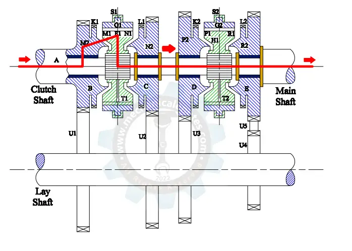
Construction of Synchromesh Gearbox:
The figure shown below explains the construction and working of the Synchromesh Gearbox.
Earlier, the synchromesh devices were fitted only to the higher gears. But for the reverse gear and lower gears, ordinary dog clutches are provided and it is done to reduce the cost of the gearbox.
The figure shown below consists of Gears B, C, D, and E attached to the main shaft A and are free to rotate and are always in mesh with the gears on the layshaft.
As long as the main shaft A rotates, the gears connected with the main shaft also rotate.
The synchromesh device is placed in between the two Gears similar to dog clutches in a constant mesh gearbox
The following terms are related to the synchromesh device and also the gears surrounded by it.
F1 & F2 → Free to slide on Splines
G1 & G2 → Ring Shaped members having internal teeth fits on to the external teeth of F1 & F2.
K1 & K2 → Dog teeth on B & D resp.
L1 & L2 → Dog teeth on C & E resp.
S1 & S2 → Forks (Gear changing levers)
T1 & T2 → Balls supported by Springs.
M1, M2, N1, N2, P1, P2, R1, and R2 → Frictional surfaces.
How synchromesh gearbox works?
The gears B, C, D, and E are placed on the bearings (black color) connected to the main shaft.
The Synchromesh Device which has internal splines are placed in between the two gears and also placed on the external splines of the main shaft. The internal gear G1 meshes with external gear F1.
Power Transmission by the First Gear:
when the main shaft A rotates, the power will be transferred to the gear U3 of the layshaft which rotates Gear D of the main shaft.
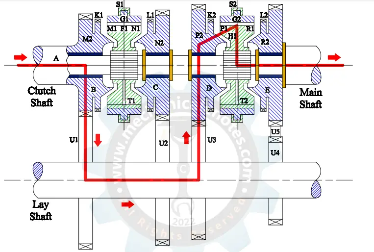
Now for the engagement of the gear D, the synchromesh device has to be slid towards the left with the help of Fork S2 so that the tapered surface P1 and P2 mesh with each other.
Note: The Power Transmission will take place after the meshing of P1 and P2 only which was not shown in the figure.
As the P2 is moving with some speed, the same speed will be given to the P1 because they are in contact with each other. Hence the synchromesh device starts rotating.
The internal gear G2 which is attached to the F2 also slides towards the left so that it can mesh onto the Gear K2.
Now, after meshing, the power is to be transferred from
B→ U1→ U3→ D→ F2→ Splines→ Main shaft.
Power Transmission by the Second Gear:
When the Main shaft A rotates, the power will be transferred to the gear U2 of the layshaft which rotates Gear C of the main shaft.
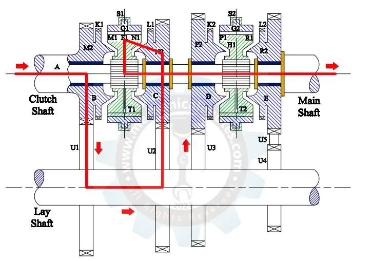
Now for the engagement of the gear C, the synchromesh device has to be slid towards the right with the help of Fork S1 so that the tapered surfaces N1 and N2 mesh with each other.
Note: The Power Transmission will take place after the meshing of N1 and N2 only which was not shown in the figure.
As the N2 is moving with some speed, the same speed will be given to the N1 because they are in contact with each other. Hence the synchromesh device starts rotating.
The internal gear G1 which is attached to the F1 also slides towards the right so that it can mesh onto the Gear L1.
Now, after meshing, the power is to be transferred from
B→ U1→ U2→ C→ F1→ Splines→ Main shaft.
Power Transmission by the Third Gear:
When the Main shaft A rotates, the power will be transferred to gear B of the main shaft.
Now for the engagement of gear B, the synchromesh device has to be slid towards the Left with the help of Fork S1 so that the tapered surface M1 and M2 mesh with each other.
Note: The Power Transmission will take place after the meshing of M1 and M2 only which was not shown in the figure.
As the M2 is moving with some speed, the same speed will be given to the M1 because they are in contact with each other. Hence the synchromesh device starts rotating.
The internal gear G1 which is attached to the F1 also slides towards the Left so that it can mesh onto the Gear K1.
Now, after meshing, the power is to be transferred from
B→ F1→ Splines→ Main shaft.
Power Transmission by the Reverse Gear:
when the main shaft A rotates, the power will be transferred to the gears U4 and U5 of the layshaft which rotates Gear E of the main shaft.
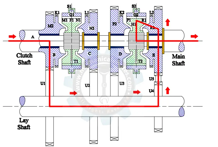
Now for the engagement of the gear E, the synchromesh device has to be slid towards the Right with the help of Fork S2 so that the tapered surfaces R1 and R2 mesh with each other.
Note: The Power Transmission will take place after the meshing of R1 and R2 only which was not shown in the figure.
As the R2 is moving with some speed, the same speed will be given to the R1 because they are in contact with each other. Hence the synchromesh device starts rotating.
The internal gear G2 which is attached to the F2 also slides towards the Right so that it can mesh onto the Gear L2.
Now, after meshing, the power is to be transferred from
B→ U1→ U4→ U5→ E→ F2→ Splines→ Main shaft.
Advantages of Synchromesh Gearbox:
The advantages of Synchromesh Gearbox are as follows.
- The biggest disadvantage of the Constant Mesh Gearbox has been solved by the Synchromesh Gearbox i.e. Double-Declutching.
- The noise problem during the engagement of Gears has been minimized in the Synchromesh Gearbox.
- Due to the presence of Synchronizers, the quick-shifting of gears is possible.
- During transmission, there is no loss of Torque due to the presence of synchronizers.
Disadvantages of Synchromesh Gearbox:
The disadvantages of Synchromesh Gearbox are as follows.
- Improper gear changing will lead to the failure of gears.
- It is expensive compared to the other gearbox due to the usage of Synchronizers.
- Where cost is the consideration, synchronizers can only be used for higher gears whereas dog clutches are used for lower gears and Reverse gears.
Applications of Synchromesh Gearbox:
The applications of Synchromesh Gearbox are as follows.
The disassembly of Synchromesh Gearbox has been used in the Vehicles of Swaraj Mazda.
Difference between Synchromesh Gearbox and Constant Mesh Gearbox:
The difference between Synchromesh Gearbox and Constant Mesh Gearbox are as follows.
| Synchromesh Gearbox | Constant Mesh Gearbox |
|---|---|
| Synchronizers are used to engage and disengage gears | Dog clutches are used to engage and disengage. |
| There will be no slip in the case of Synchromesh Gearbox | There will be the presence of slip in the case of Constant-mesh Gearbox |
| The locking action was fully satisfied by Synchromesh Gearbox | The locking action was partially satisfied by Constant Mesh Gearbox |
- In the case of Synchromesh Gearbox, Synchronizers are used to engage and disengage gears whereas, in Constant-mesh Gearbox, dog clutches are used to engage and disengage.
- The locking action was fully satisfied by Synchromesh Gearbox whereas it was absent by the use of dog clutches in Constant-mesh Gearbox.
- There will be no slip in the case of the Synchromesh Gearbox whereas Slippage takes place in the Constant Mesh Gearbox.
This is a detailed explanation of the Synchromesh Gearbox. If you have any doubts, you can ask in the comments section.
More Resources:
Sliding Mesh Gearbox
Constant Mesh Gearbox
External Links:
Media Credits:
- Image 1: By A7N8X - Own work, CC BY-SA 3.0, https://commons.wikimedia.org/w/index.php?curid=7997162
- Remaining Images: Admin releases all rights but a photo credit would be appreciated if this image is used anywhere on any platform. Thank you!