Constant Mesh Gearbox: Components, Working Principle, Advantages, Disadvantages, Applications [PDF]
This is one of the transmission systems in automobiles which is advanced of Sliding Mesh Gearbox. Constant Mesh Gearbox will come under Manual Transmission and overcome the limitations of Sliding Mesh Gearbox, the Constant Mesh Gearbox has come into the picture.
There are 3 types of Gearbox present in the subject of Automobile Engineering. They are
- Sliding Mesh Gearbox
- Constant Mesh Gearbox
- Synchromesh Gearbox
The detailed explanation of Constant Mesh Gearbox is as follows.
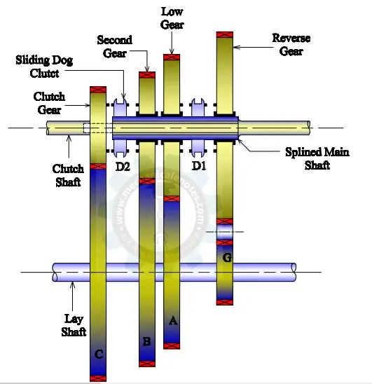
Line Diagram of Constant Mesh Gearbox:
The line diagram of the Constant Mesh Gearbox is shown below.
Introduction of Constant Mesh Gearbox:
As the name indicates that all the gears on the layshaft and main shaft are in constant mesh with each other and the dog clutch decides the transmission of the required gear to be engaged.
For the smooth engagement of dog clutches, it is required that the speed of the main shaft gears and the dog clutch must be equal.
Therefore to obtain lower gear, the speed of the layshaft, clutch shaft, and the main shaft must be increased.
The shifting of gears was not at all an easy task and only a skilled driver can drive such a vehicle the special technique required was Double-declutching.
Double-Declutching:
Case 1: (To engage from 3rd to 2nd gear i.e. higher to lower)
Firstly Clutch is pressed, then the gear lever is set to be in a Neutral Position. Now the speed of the 3rd gear is less compared to the dog clutch and the speed of the 3rd gear has to be increased by pressing the accelerator pedal.
When the speed of 3rd gear is equal to the speed of the dog clutch, then the clutch pedal is pressed again for the change of a Gear.
Representation of Case 1:
Clutch is pressed-->Gear is set to Neutral Position-->Speed of Dog clutch > Speed of 2nd gear-->Speed of 2nd gear is to be increased by Accelerator -->Now, when both the speeds are equal, then press the clutch and engage with a Gear.
Case 2: (To engage from 1st to 2nd gear i.e. lower to higher)
Clutch is pressed-->Gear lever is set to Neutral Position --> Speed of Dog clutch < Speed of 2nd gear -->Speed of 2nd gear is to be decreased by releasing the clutch pedal. Now, when both the speeds are equal, then press the clutch and engage with a Gear.
So, in this way, double-declutching is taking place in the case of Constant Mesh Gearbox.
The detailed information on Constant Mesh Gearbox is as follows.
Components of Constant Mesh Gearbox:
The components of Constant Mesh Gearbox are as follows.
- Shafts
- Clutch shaft
- Lay Shaft
- Main Shaft
2. Gear Lever
3. Dog clutch
4. Gears
- Fixed Gears
- Movable Gears
- Idler Gear
- Clutch Gear
An explanation for the components of Constant Mesh Gearbox:
The explanation is as follows...
#1 Shafts:
The shaft is generally used to transmit power from one end to another end. There are three types of shafts in the case of Sliding Mesh Gearbox.
Clutch Shaft:
The clutch shaft is used to transmit the power from the engine when the clutch is in an engaged position. When the clutch shaft is rotating, the clutch gear which is attached at the end of it also rotates along with the clutch shaft.
Main Shaft:
This shaft acts as an output shaft for the transmission of power from the engine shaft via a layshaft. The gears with internally splined grooves are arranged on the main shaft so that they can mesh easily with the gears of the layshaft.
Lay Shaft:
The layshaft is an intermediate shaft between the clutch shaft and the Main shaft which provides meshing of fixed gears to the movable gears to provide the output appropriately.
The fixed gears are attached to the layshaft and they are in mesh with the gears of the main shaft and the gear of the clutch shaft.
#2 Gear Lever:
This lever is used by the driver to change the gear by employing a selective mechanism.
#3 Dog Clutch:
The dog clutch is used to engage and disengage the gears on the main shaft for transmission of power.
#4 Gears:
Fixed Gears:
These gears are attached to the layshaft for a proper mesh with the gears of the main shaft. As they are fixed, if one gear rotates then all the gears rotate along with the layshaft also.
Movable Gears:
These gears are attached to the Main shaft and are independent. It means, that if one gear rotates, then other gears do not rotate w.r.t. the shaft. As the vehicle has to move in any of one gear (might be 1st,2nd, and 3rd), there is no need for the rotation of another gear.
Idler Gear:
This gear is used when the vehicle needs to move in the reverse direction. This gear places its position in the center of layshaft gear and main shaft gear and thus the reverse action is taking place in the vehicle.
Clutch Gear:
This gear is attached at the end of the clutch shaft for transmitting power from the engine to the layshaft and main shaft respectively.
Working Principle of Constant Mesh Gearbox:
The Sliding Mesh Gearbox uses Spur Gears for the transmission of power from the engine shaft to the main shaft whereas the Constant Mesh Gearbox uses helical gears.
This system generally consists of 3 shafts i.e. Clutch shaft, the layshaft, and Main Shaft. Apart from this, 2 dog clutches are mounted on the main shaft for engaging with the gears desired by the driver.
The power comes from the engine to the clutch shaft and thence to the clutch gear which is always attached at the end of the clutch shaft. All the gears on the layshaft are fixed and are in mesh with the clutch gear and main shaft gears.
Let's understand how the gears mesh for the transmission of power.
Note: Here, the driving shaft is the Layshaft and the driven shaft is the Main shaft.
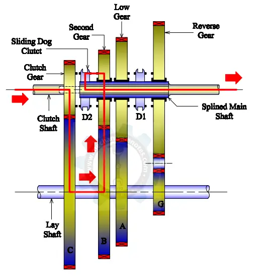
Power Transmission by the First Gear (A):
As you know that the vehicle moves slowly in the first gear compared to all the other driving gears this is because the gear of the driving shaft (layshaft) is small compared to the gear of the driven shaft (Main Shaft).
Due to this, it acquires maximum torque at low speed and this can be obtained, when the driver pulls the gear lever for the 1st gear, the dog clutch(D1) slides towards its left on the main shaft and meshes with the 1st gear. Thereby the power is transmitted via the first gear (A).
Representation of Power Transmission in 1st Gear:
For the Representation, look at the figure.
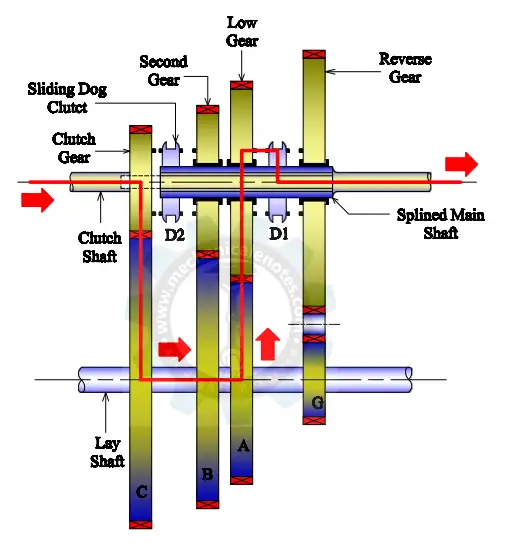
Note: The power will be transmitted after the engagement of Dogclutch which was mentioned in the figure
The power is transmitted from the Clutch shaft to Gear A mounted on the layshaft. You can see that the dog clutch (D1) is engaging with the lower gear on the main shaft and the power transmission takes place from the dog clutch to the splines and the main shaft which was represented below.
Clutch Shaft--> Gear A--> D1-->Splines-->Main Shaft.
Power Transmission by the Second Gear (B):
The Torque acquired is smaller and the speed acquired is larger than the first gear and this can be obtained when the driver pulls the lever for the 2nd gear.
The dog clutch (D2) slides towards its right and engages with the 2nd gear on the main shaft. Thereby the power is transmitted via the second gear to the other parts of the transmission system.
Representation of Power Transmission in 2nd Gear:
For the Representation, look at the figure.
The power is transmitted from the Clutch shaft to Gear B mounted on the layshaft. You can see that the dog clutch (D2) is engaging with the second gear on the main shaft and the power transmission takes place from the dog clutch to the splines and the main shaft which was represented below.
Clutch Shaft-->Gear B-->D2-->Splines-->Main shaft.
Power Transmission by the Third Gear (C):
The third Gear provides Maximum speed and Minimum Torque compared to the 2nd gear and is obtained when the driver pulls the lever for the 3rd gear.
The dog clutch (D2) slides towards its left and engages with the 3rd gear on the main shaft which is in direct contact with the clutch shaft.
Thereby the power is transmitted via the third gear to the other parts of the transmission system.
Representation of Power Transmission in 3rd Gear:
For the Representation, look at the figure below.
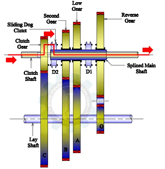
The power is transmitted from the Clutch shaft to the clutch gear which is attached at the end of it. You can see that the dog clutch (D2) is engaging with the clutch gear on the main shaft and the power transmission takes place from the dog clutch to the splines and the main shaft which was represented below.
Clutch Shaft--> Clutch Gear-->D2--> splines-->Main shaft.
Power Transmission by the Reverse Gear:
Here the idler gear is to be placed in between the bigger diameter gear of the main shaft and the smaller diameter gear (G) of the layshaft. Therefore, the vehicle moves in a reverse direction.
Representation of Power Transmission in Reverse Gear:
For the Representation, look at the figure below.
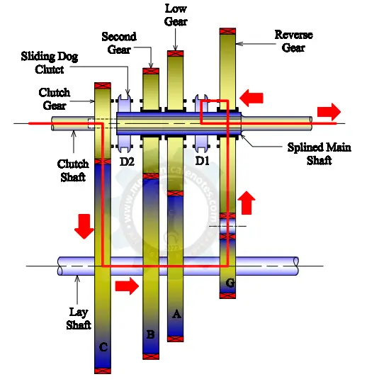
The power is transmitted from the Clutch shaft to Gear G mounted on the layshaft. You can see that the dog clutch (D1) is engaging with the Reverse gear on the main shaft and the power transmission takes place from the dog clutch to the splines and the main shaft which was represented below.
Clutch Shaft-->Gear G-->D1-->Splines-->Main shaft.
In this way, by the usage of 3 forward gears and 1 reverse gear, the power transmission takes place in the Constant Mesh Gearbox.
Note:
As per the diagram of Textbook referred above, we have 3 forward gears and 1 reverse gear whereas, if the same concept is to be applied to heavy vehicles, then just increase the gears and dog clutches i.e. for 6 gear vehicle, 5 are Forward gears and 1 is the reverse gear where in this case, 3 dog clutches are used.
For 5 gear Vehicle, 4 are forward gears and 1 is the reverse gear and especially in this case , there is no alignment of Dog clutch with the reverse gear. A special gear arrangement was made where 2 dog clutches are used for 4 gears and a combination of three gears(a gear on main shaft, pinion gear and the gear on layshaft) was added so that the power transmission takes place without the engagement of dog clutch.
Advantages of Constant Mesh Gearbox:
The Advantages of Constant Mesh Gearbox are as follows.
- There is no need for straight spur gears because the gears were always in mesh in the case of a constant mesh gearbox. Instead, helical gears will be used which are quiet running.
- Helical gears are used in this system to avoid vibrations during the engagement.
- During engagement and disengagement, the wear of dog teeth is reduced because all the teeth of dog clutches are involved in the meshing when compared to the sliding gears where only 2 or 3 teeth were under the mesh.
- The noise level was very low and Mechanical Efficiency was very high compared to Sliding Mesh Gearbox.
Disadvantages of Constant Mesh Gearbox:
The Disadvantages of the Constant Mesh Gearbox are as follows.
- To avoid little vibrations taking place during the engagement of the dog clutch with the gears on the main shaft, it is advised to use synchronizers which can reduce the effect of the vibrations.
- Double declutching was the biggest disadvantage of Constant Mesh Gearbox which was already explained above.
Applications of Constant Mesh Gearbox:
The applications of Constant Mesh Gearbox are as follows.
- The constant-mesh gearbox was mainly used in heavy machinery, farm trucks, motorbikes, etc.
- Ford Model T uses Constant Mesh Gearbox.
- Before the introduction of the synchromesh gearbox in 1928 by General Motors, the Constant Mesh Box was used in motorbikes also.
Difference between Constant Mesh Gearbox and Synchromesh Gearbox:
The difference between Constant Mesh Gearbox and Synchromesh Gearbox is as follows.
| Constant Mesh Gearbox | Synchromesh Gearbox |
|---|---|
| Dog clutches are used to engage and disengage gears | Synchronizers are used to engage and disengage gears |
| The locking action of dog clutches was absent in Constant-mesh Gearbox | The locking action was fully satisfied by Synchromesh Gearbox. |
| Slip takes place in the Constant Mesh Gearbox | There will be no slip in the case of Synchromesh Gearbox. |
This is a detailed explanation of Constant Mesh Gearbox. To avoid Double declutching and noise, Synchromesh Gearbox has come into existence.
More Resources:
Sliding Mesh Gearbox
Synchromesh Gearbox
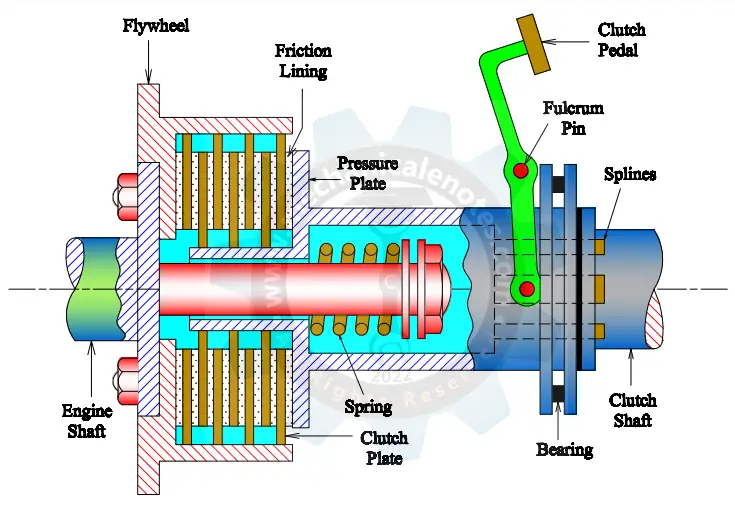
Types of Clutches-Single Plate Clutch, Electromagnetic clutch, Cone Clutch
External Links:
Media Credits:
- All the images along with the Feature image are modified by the Admin. If you want to take any image, credit is expected from your end.