Manual Transmission Parts and Function [PDF]
In the last session, we had discussed Epicyclic Gearbox, Overdrive in Automobile and Torque tube drive. Whereas in todays session, we will discuss Manual Transmission Parts and Function in a detailed way.
Manual Transmission Parts and Function:
Before discussing the Manual Transmission and function , Let's discuss What is Manual Transmission and How does it works?
What is Manual Transmission?
A manual transmission is a gearbox that allows the driver to select from various gear ratios when driving the car. Lower gear ratios provide more torque but slower speeds, whereas higher gear ratios provide less torque but faster speeds.
A "six-speed" manual transmission has six forward gear ratios because different gear ratios are referred to as "speeds.
The manual transmission is made up of three shafts with constantly-intermeshed gears of various sizes. The clutch connects the input shaft to the engine. The countershaft contains many gears and is constantly meshed with the input shaft.
The output shaft connects the countershaft to the driveshaft, which connects the wheels. The output shaft links to the transfer case first in four-wheel drive and all-wheel drive vehicles. To change direction, reverse gear is mounted on a fourth shaft.
The gears themselves are freewheeling and are not attached to the output shaft. On the other hand, locking collars spin with the output shaft and can shift or slide back and forth to engage one of the gears. It's for this reason that we term it "shifting" gears.
The input shaft and countershaft are rotating, as are the output shaft gears, in "neutral," with no gear chosen and the clutch released, but the output shaft does not move since none of the locking collars are engaged. The countershaft connects to the driveshaft, and then to the wheels.
How Does A Manual Transmission Work?
For example, the driver depresses the clutch and disengages the input shaft to shift gear when engaging first gear. The driver enters first gear with the gearshift lever, and the linkage advances the gearshift fork from first to second gear.
The locking collar must be connected to the first gear and locked to the output shaft. Because 1st gear is connected to the output shaft by the locking collar, if the clutch is released and the input shaft engages, the output shaft turns. If the driver accelerates, the process is repeated when shifting to second gear, but the gearshift lever is shifted to second gear.
The input shaft is re-engaged when the clutch is released, and power is transmitted through 2nd gear this time. A second shift linkage, a shift fork, and a locking collar are utilized between 3rd and 4th gear while shifting into 3rd gear. Because the countershaft and output shaft move at different rates, shifting from first to second gear is difficult.
Attempting to change into a higher gear when the car slows down is equivalent to turning the shaft at two different speeds, which is impossible. Synchronizer rings work like small clutches, using friction to bring the circlip and gear up to speed. They will readily interlock at this point.
Types of Manual Transmission:
1. Sliding Mesh Gearbox:
The Sliding Mesh Gearbox was the first automotive gearbox or transmission system. The world's largest-ever transmission system with 3-speed sliding mesh transmission was designed by French Inventors Louis-Rene and Emile Levassor in 1894.
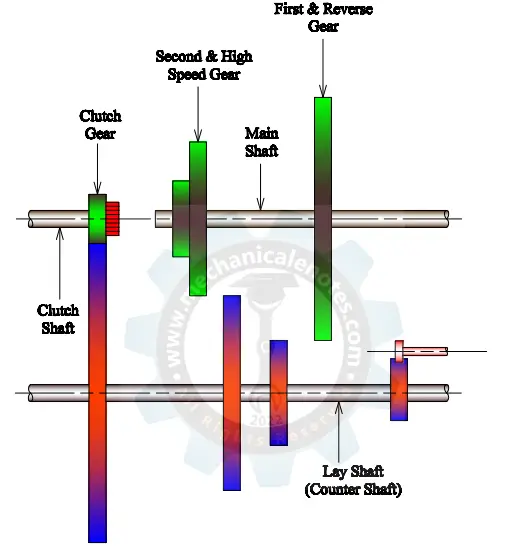
The desired gear ratio is obtained by sliding the required gears and the appropriate matching gears. A sliding mesh gearbox is a transmission system of several sets of gears and shafts arranged logically. The shifting or meshing of different gear ratios is accomplished by moving gears to the right and left across the splined shaft with the help of a gear lever actuated by the driver.
The gears on the layshaft are securely fixed to the shaft, but the gears on the main shaft can glide on it via splines but are otherwise in permanent rotational mesh with the shaft.
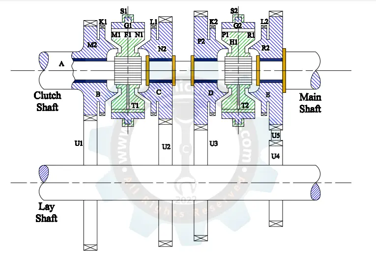
2. Constant Mesh Gearbox:
A constant mesh gearbox is used to keep an automobile running smoothly. It increases the spinning force (Torque) while lowering the speed. It's a manual transmission kind. In the nineteenth century, the first manual gear system was invented.
Several gear ratios are available, each producing a different torque and speed ratio. Additionally, the reverse mechanism is present. All of the gears mesh at any given time in the manual transmissions that have lately been designed.
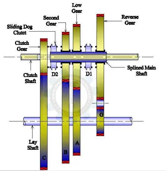
A dog clutch is used to shift gears and calculate gear ratios in the constant-mesh gearbox. A clutch shaft, layshaft, countershaft, and output or main shaft make up the constant mesh gear. All gears on the main shaft and countershaft are connected in this system.
A mechanism called a dog clutch is utilized to achieve the gear ratio. The gear is attached to the dog clutch for the desired speed and gear ratio.
3. Synchromesh Gearbox:
It's a manually driven transmission that switches gears between gears already spinning at the same speed. The gears in this gearbox can revolve freely or be locked on the layout shaft. The synchronizer is the most important component of this gearbox since it regulates the speed.
A synchronizer is a clutch that allows parts to rotate at different rates. Cone friction is utilized to synchronize the speeds. Synchro cone and balk ring are the two parts of this synchronizer. The ring is a part of the synchronizer, while the cone is a portion of the gear.
The balk ring stops the gears from engaging until they have reached the proper rotational speeds.
Manual Transmission Parts and Function:
The manual transmission system is made up of various parts. Each of them is crucial for the gearing shifting and clutch releasing abilities. You won't drive smoothly if one of these components fails.
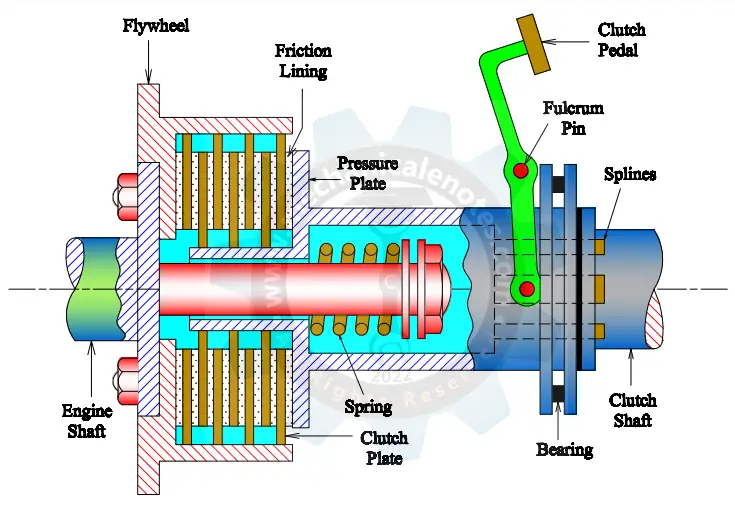
1. Clutch Disc:
A metal disc with a frictional facing, similar to brake shoes or pads, makes up the clutch disc. The lining is made of a non-organic woven or molded material with soft metal particles such as aluminum or brass. It increases the lining's strength, and a set of radial grooves on the lining's face improves the flywheel's grip on the disc.
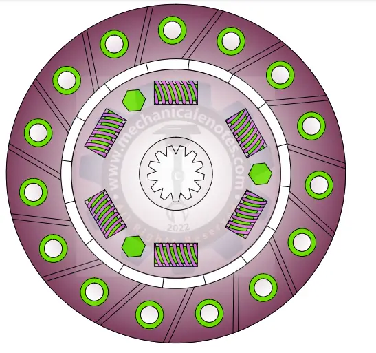
The transmission's input shaft mates with a splined hub in the disc's center, allowing direct mechanical interaction. The transmission's input shaft connects to a splined hub in the disc's center. Driveline shock and vibration are dampened by a series of torsional springs placed between the clutch hub and the lining.
The clutch disc transfers engine torque directly to the transmission's input shaft. When combined with the pressure plate and flywheel, the clutch disc controls power from the engine to the transmission.
2. Clutch Pedal:
The clutch pedal is used to disconnect the drive from the engine to the transmission. The pedal converts a parabolic clutch pedal swing into a linear movement.
This linear movement is transferred to thrust bearing movement by mechanical linkages, cable, or hydraulic fluid displacement. The friction clutch, located between the engine's flywheel and the input shaft, is activated when you step on the clutch pedal.
The clutch's job is to separate the engine from the transmission. The engine and transmission continue to spin when the pedal is pushed, but they do so independently, with no torque transfer from the engine to the gearbox, making it possible for you to shift gears.
3. Flywheel:
The clutch disc obtains torque via the flywheel, a circular component. Functions of the flywheel are
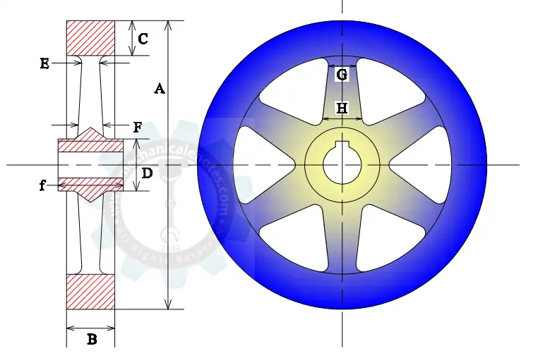
- To keep a rotational mass (inertia) to help the engine rotate and provide torque more consistently while running.
- To install a ring gear on which the starter motor can engage
- To offer one of the friction disc's driving friction surfaces.
4. Synchronizers:
The synchronizers induce engagement between the collar and the gear, allowing for synchronization of their speeds. You'll need the synchronizers to prevent this because the speeds may differ at times.
The speed of the shaft is adjusted by a synchronizer so that the gears align more quickly as you shift—the slider presses against the synchronizer's keys or balls, subsequently pressing against the blocker ring. The ring then pushes against the gear's cone, causing friction that helps to equalize shaft speeds.
A synchronizer's function is to allow meshing gears to be changed while the vehicle is driving without compromising the mechanical integrity of the gears or causing interior noise.
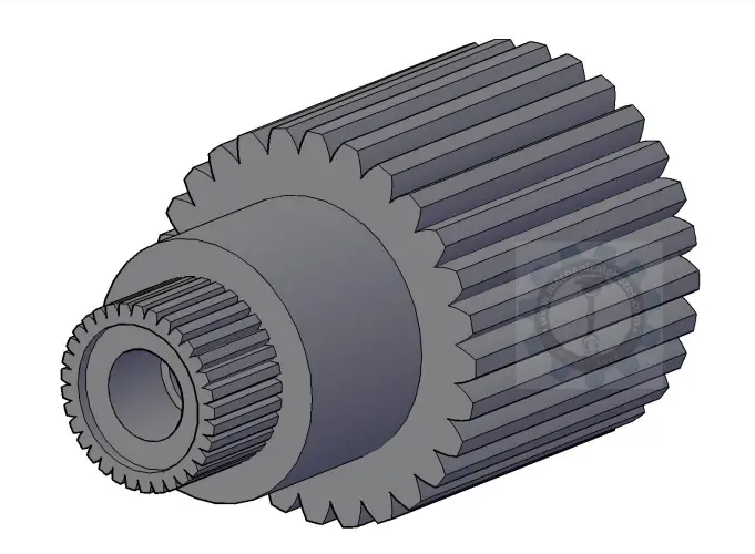
5. Gears:
The transmission has a variety of gear sizes. Big gears have a lot of teeth, while small gears have fewer teeth. Larger gears produce more torque, which helps the car slow down.
Smaller gears produce less torque, allowing the vehicle to accelerate. The amount of power available from the engine is determined by the gears.
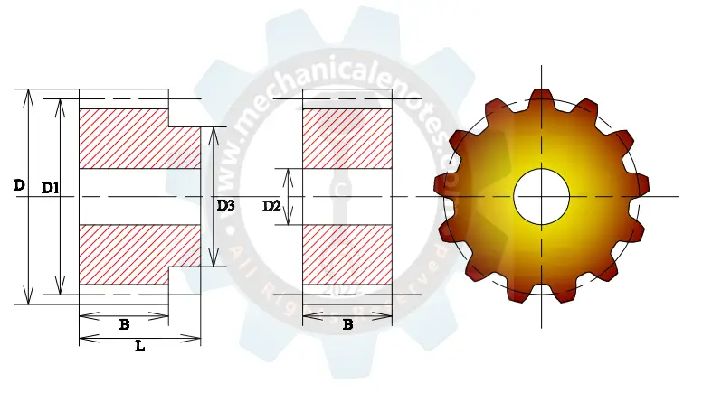
First gear has the highest pulling power but the least speed possibilities, whereas fifth gear has the least pulling strength but the widest speed range.
6. Selector Fork:
The gear selector fork includes a body forming a pair of support plates with respective coaxial through-holes for supporting the fork slidably along a stationary rod of the gearbox, a pair of prongs fixed to the body, and forming respective actuating portions able to operate a sliding coupling sleeve of the gearbox at their distal ends.
An actuating nose is fixed to the body to impart the sliding movement along the stationary rod to the fork. The body and prongs are shaped in such a way that two forks with similar bodies and prongs can be mounted on the same stationary rod and at least partially overlaid in the direction of sliding along the stationary rod.
7. Stick Shift:
It is the part that you can handle with your hand. It's the central console's vertical stick that protrudes. It is attached to the gearbox and can be used to change gears. A car with a manual or standard transmission is sometimes referred to as a stick shift. The vehicle's stick shift allows drivers to manually change ratios to accelerate the vehicle. The transmission is connected to the stick shift, placed in the car's center.
8. Collar:
The collar secures the gear selection in place and permits torque to pass to the output shaft when you pick it up.
This is the explanation of Manual Transmission Parts and Function in a detailed way.If you have any doubts, feel free to ask from the comments section and will reply you within 24hrs.
More Resources:
Slidingmesh Gearbox
Synchromesh Gearbox
Epicyclic Gearbox
Constant Mesh Gearbox
References:
1. The Manual Transmission Explained - All The Basics. (2020, October 30). The GoMechanic Blog.
2. Manual Transmission: Types, Working, Parts, Diagram - Studentlesson. (2020, July 6). Studentlesson.
3. Manual Transmission - Wikipedia. (2020, June 1). Manual transmission - Wikipedia.
4 Gearbox Components And Parts: Everything You Need To Know