Sand Casting Process: Definition, Terminology, Explanation, Advantages, Disadvantages & Applications [PDF]
The sand casting process is used for the creation of cylinder blocks, machine tool beds, pistons, etc. where you can produce the components in bulk which is not possible by means of the machining process.
All the beds of machines are large enough and cannot be prepared on any machine. Therefore, those products will be specially prepared by means of Casting only.
In this article, we will discuss Sand Casting Process: Definition, Terminology, Explanation, Aspiration Effect, Applications, etc. in a detailed way.
Definition of Sand Casting Process:
It is a process in which the liquid molten metal is poured into the casting cavity whose shape is the same as that of the shape of the casting to be produced, allowing to solidify and after solidification, the casting will be taken out by breaking the mold called as Sand Casting Process.
Terminology of Sand Casting Process:
The diagram of sand casting was presented below. It consists of
- Cope and drag
- Pouring Basin
- Sprue
- Runner
- Ingate
- Casting Cavity
- Riser
- Parting Line
- Vent
- Chaplets
An Explanation for the Terminology of Sand Casting Process:
A detailed explanation of the above sand casting terms is presented below.
1.Cope and Drag:
The Top Flask is called a Cope and the bottom Flask is called Drag.
2. Pouring Basin:
- The molten metal is to be poured into the Pouring basin so that it can enter into the mold cavity.
- The pouring basin separates the impurities[lighter and heavier impurities present in the molten material]
- The size and shape of the pouring basin will not have much effect on the flow rate or pouring time of molten metal in the gating system.
3. Sprue:
It is connecting the passage between the pouring basin and Runner. It is always vertical with a straight tapered circular cross-section.
Characteristics of Sprue:
Basically, the Velocity of molten metal in the gating system is represented by
V = Sqrt.2gh
Where ‘h’ is the height of the sprue.
The height of the sprue is mainly responsible for producing the velocity of molten metal in a gating system. The height of the sprue is selected such that the velocity of molten metal in the gating system must always ensure laminar flow.
Straight tapered sprue is selected to avoid the aspiration effect in the gating system.
Other Elements in Sprue:
Strainer:
- Always kept in sprue only.
- It is used for separating/filtering the impurities present in the molten metal.
- It is made by using a Ceramic material with high porosity.
Splash Core:
- Used for avoiding sand erosion from the bottom of Sprue.
- Also made by using a Ceramic material with low porosity.
Skim Bob:
- It is a Semi circular-cut given in Runner.
- It is used for separating Impurities present in molten metal.
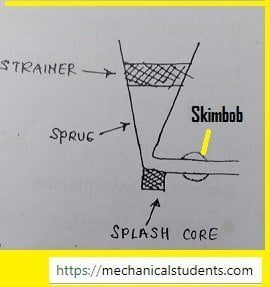
By these additional elements in Sprue, all possible impurities are separated from the molten metal.
4. Runner:
- It is a connecting passage between the bottom of the Sprue and in-gate.
- The runner is always horizontal with a uniform Trapezoidal Cross section.
- It is mainly used for minimizing the sand erosion in the casting process.
Qactual = Cd*Qtheoretical
A trapezoidal cross-section has the highest value of the coefficient of discharge(Cd) and for that reason, it is selected for the design of a runner.
5. Ingate:
It is the last section of the gating system from where the molten metal is entering into the casting cavity. It is also horizontal and uniform trapezoidal in cross-section.
6. Casting Cavity:
It is the cavity in which the molten metal is filled and solidified in order to get the desired product.
7. Riser:
The riser is acting as a Reservoir for supplying the molten metal to the casting cavity for compensating the liquid Shrinkages taking place during solidification.
8. Parting Line:
It is the line that divides the Cope and Drag.
9. Vents:
It is a small opening in the mold to escape the gases during solidification.
10. Chaplets:
Chaplets are used to support the cores inside the mold cavity to take care of their own weight.
11.Core:
To get hollow parts from the casting process, the core is to be placed in the casting cavity such that molten metal surrounds around the core and thereby we get a hollow component.
Sand Casting Process Diagram:
The diagram of the Sand Casting Process was presented below.
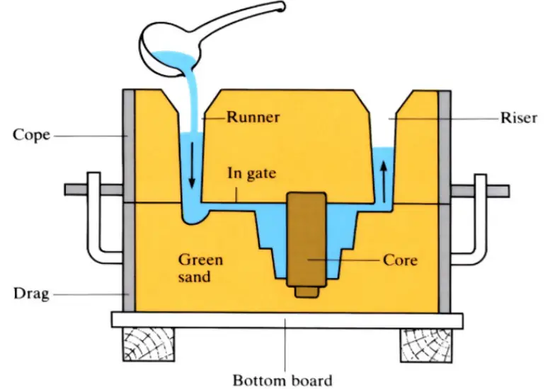
Explanation of Sand Casting Process:
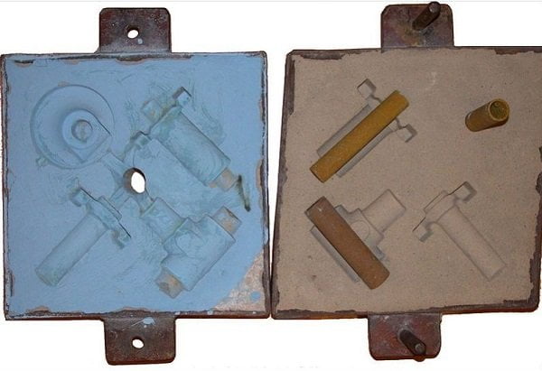
Sand is to be rammed in Cope and Drag which are metal boxes and are to be placed one on the other.
In the Cope box, the passages will be created with the help of the Sprue pin and the Riser pin whereas, in the Drag box, the casting cavity will be created by placing the pattern.
As we have two patterns. One is a Solid piece pattern and the other is Split Pattern.
In the case of the Solid Piece pattern, you need to place a solid pattern in the Drag box only whereas for the Split pattern, two patterns are to be placed. Among the two, one is placed in the Cope box and the other is to be placed in the drag box.
The patterns, sprue, riser are to be removed from the molding boxes such that cavities or passages will form.
Now, the two boxes i.e. cope and drag are to be placed one on the other and the molten metal is to be poured into the casting cavity from the Pouring basin.
The pouring basin separates the impurities I.e.lighter and heavier impurities present in the molten material are removed at the initial stage only.
Next, the molten metal passes through various channels such as Sprue, runner, Ingate and finally casting cavity.
The Sprue is a connecting passage between the pouring basin and the Runner. It should be always vertical with a straight tapered circular cross-section.
Next, molten metal enters into the Runner.
- Runner is always horizontal with uniform Trapezoidal Cross section.
- It is mainly used for minimizing the sand erosion in the casting process.
After that, molten metal enters into the Ingate.
- Ingate is the last section of the gating system from where the molten metal will enter into the casting cavity.
- Ingate is also horizontal and of uniform trapezoidal in cross-section.
Finally, molten metal enters into the Casting cavity where solidification takes place within each and every corner and after that, the remaining molten metal will come out through the riser.
The riser will also act as a Reservoir for supplying the molten metal to the casting cavity for compensating the liquid Shrinkages taking place during solidification.
After some time, the fetling has to be done i.e. breaking the sand mold and taking out the cast part.
So, in this way, the component is prepared from Sand Casting Process.
Aspiration Effect or Inhalation Effect in Sand Casting:
During filling of molten metal into the casting cavity using gating system somewhere along with the gating system due to some reason, if the pressure falls below atmospheric pressure, the pressure difference is existing between the inside and outside of gating system.
Due to this pressure difference, the air starts flowing from outside to the inside of the gating system through the Porosity property of molding sand called an aspiration effect.
Sand Casting Process Advantages:
The Advantages of the Sand Casting Process are as follows.
- The cost for the component to be produced is less compared to other processes.
- High surface finish can be obtained from the cast parts.
- Easy availability of raw materials for the formation of molten metal.
Sand Casting Process Disadvantages:
The disadvantages of the sand casting process are as follows.
- Not at all suitable for low volume production.
- Due the presence of porous layers or holes, the strength decreases compared to forged component.
Sand Casting Process Applications:
The Applications of the Sand Casting Process are as follows.
- All the beds of machines (lathe bed) are prepared from the sand casting process.
- Aluminum, steel, iron, manganese, etc. are some of the metals which are converted into a molten form for the preparation of machine components.
- The components which are not possible by the machining process are done by the casting process.
- The sand casting process is used for the creation of cylinder blocks, machine tool beds, pistons, etc.
This is all about the sand casting process, I hope you liked my article, if you have any doubts don't forget to comment down below, and do not forget to share this stuff with your friends.
References [External Links]: