Diesel Cycle: Process, PV Diagram, Efficiency with Derivation & Applications [Explanation & PDF]
In this article, the working of 4 Stroke CI engine will be discussed first and later the 4 processes employed in the Diesel cycle will be provided along with its derivation to calculate the Efficiency of Diesel cycle.
So as I said to understand the Diesel Cycle you need to know about the four-stroke which occurred into the CI Engine.
The 4 stroke CI engine is similar to the 4 stroke Si engine but, it operates at a much high compression ratio.
The compression ratio of the CI engine varies from 16 to 20 whereas the SI engine varies from 6 to 10.
Due to the high compression ratio employed, the temperature at the end of the compression stroke is sufficiently high to self Ignite the fuel which is injected into the combustion chamber.
The major differences are that the ignition occurs spontaneously due to the high temperature of the compressed air that is ignited by means of a fuel injector.
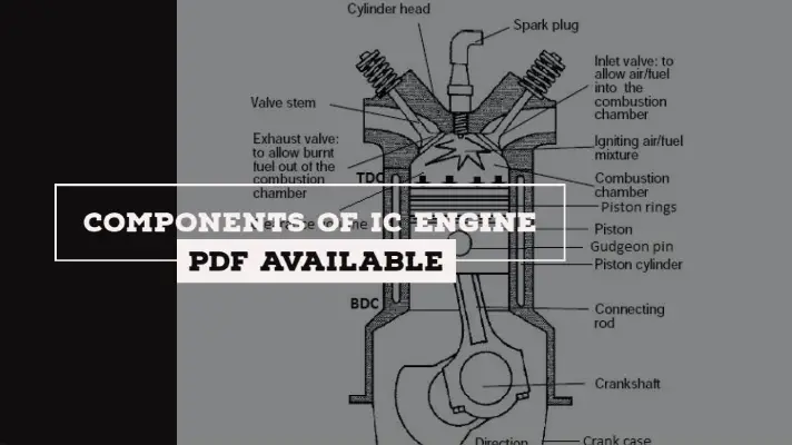
Explanation of Four Strokes Occured in Diesel Engine:
The sequence of operations in a four-stroke CI engine (diesel engine) is as follows.
- Suction Stroke
- Compression Stroke
- Expansion Stroke
- Exhaust Stroke
The explanation of the above operations is as follows.
Note:
I.P stands for Inlet Port
E.P stands for Exhaust Port
F. I stands for Fuel Injector
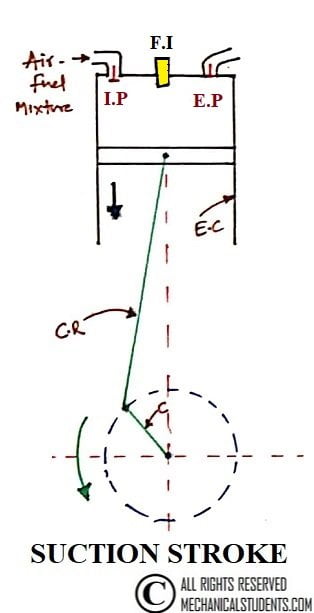
1. Suction Stroke:
During suction stroke only, Air is admitted into the cylinder. In this stroke, the inlet valve is opened and the exhaust valve is closed and the piston travels from TDC to BDC.
2. Compression Stroke:
here the inlet valve and the exhaust valve will remain closed. The Piston moving upward compresses the air to high pressure and temperature.
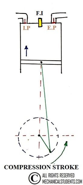
Fuel is injected into the cylinder at the end of the compression stroke and ignition occurs spontaneously due to the high temperature of the compressed air.
3. Expansion Stroke:
Burning of fuel results in the release of chemical energy which increases the pressure and thus results in moving the piston from TDC to BDC.
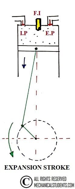
This process is the expansion process where the piston comes down to BDC(Bottom Dead Center) with both inlet and exhaust valves in a closed position.
4. Exhaust Stroke:
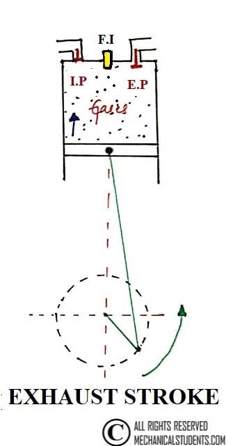
The Piston traveling from bottom dead Centre to Top Dead Centre pushes out the products of combustion through the exhaust valve, which is opened.
This is the detailed Explanation of Four Strokes Occured in Diesel Engine.
Understand the concept very carefully with gif file and the Youtube Video presented below.
So now I hope you are able getting the working of Diesel Engine, so now let's dive into the working cycle.
Explanation of Diesel Cycle:
This cycle was introduced by Dr. D.R.Diesel in 1897.
In the Diesel cycle, heat is supplied at Constant Pressure whereas, in Otto Cycle, heat is supplied at Constant Volume.
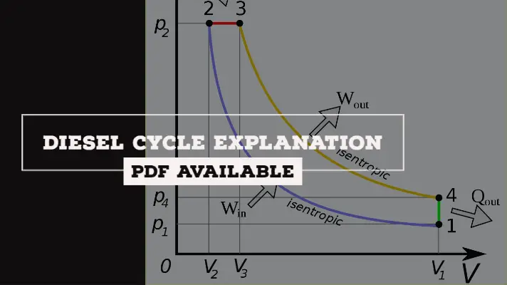
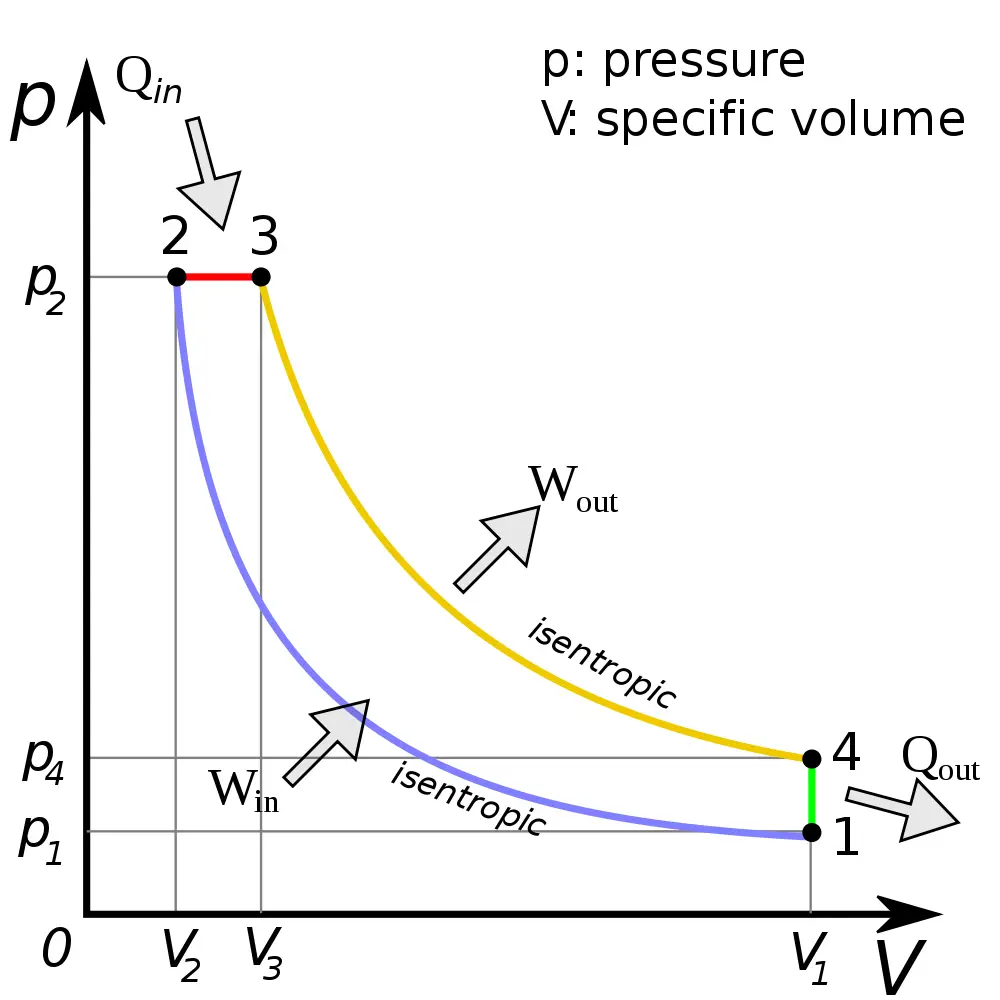
Diesel cycle comprises of 4 processes.
- Process 1-2: Reversible Adiabatic Compression
- Process 2-3: Constant Pressure heat supply
- Process 3-4: Reversible Adiabatic Expansion
- Process 4-1: Constant Volume Heat Rejection
Process 1-2: Reversible Adiabatic Compression
It is also known as a reversible adiabatic compression process. At point 1, the cylinder is full of air. Let P1, V1, T1 be the corresponding Pressure, volume, and temperature.
Air is compressed by the piston to high pressure and temperature till the values become P2, V2, and T2.
Process 2-3: Constant Pressure heat supply
It is also known as a constant pressure heat supply process.
In this process, heat is supplied to air at constant pressure from the hot body and thereby there is an increase in the temperature from T2 to T3 and Volume from V2 to V3.
Qs = mCp(T3-T2)
Process 3-4: Reversible Adiabatic Expansion
It is also called a reversible adiabatic expansion process. In this process, at point 3, the supply of heat is stopped and this point is known as Point of Cut off. Later, the air expands to the conditions of P4, V4 and T4 respectively corresponding to point 4.
This indicates the work is done by the gas due to the expense of internal energy and there will be no heat transfer in this process.
Process 4-1: Constant Volume Heat Rejection
It is also called a constant volume heat rejection process. In this process, air rejects the heat to the cold body at constant volume till point 1 where it returns to its original state.
In this process, Temperature decreases from T4 to T1 and Pressure decreases from P4 to P1.
QR =mCv(T4-T1)
Derivation of Diesel Cycle:
In this derivation, the efficiency of the Diesel cycle is calculated.
The P-V and T-S Diagram of the Diesel cycle are presented below.
Considering 1 Kg of Air,
Work done = Heat Supplied - Heat Rejected= mCp(T3-T2) - mCv(T4-T1)
Efficiency = Work done/Heat Supplied
The rest of the derivation is written below:
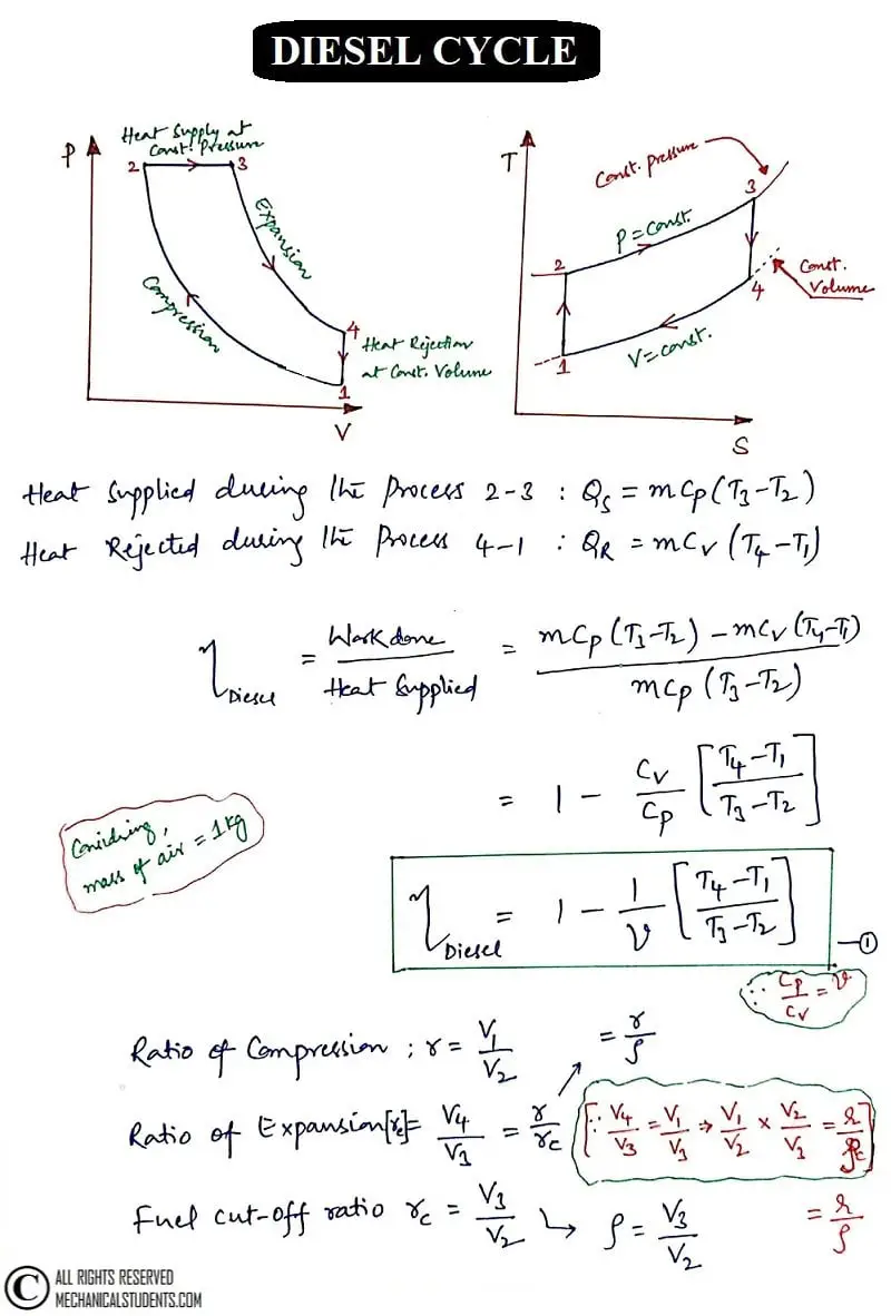
Now, Considering Adiabatic Compression from 1-2 and Adiabatic Expansion from 3-4, the efficiency of the Diesel Engine can be obtained from Diesel Cycle.
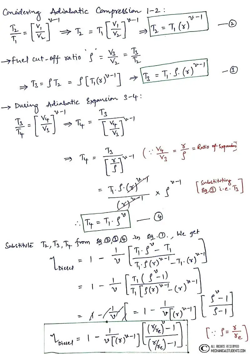
This is the efficiency of the Diesel Cycle.
Applications of Diesel Cycle:
The Applications of Diesel Cycle are as follows.
- Of any large internal combustion engines, Diesel engines have the lowest Specific Fuel Consumption.
- The diesel engines will be used in Trucks, rollers, excavators, diesel generators, farming equipments, buses etc.
- The engines of Diesel is large than the Petrol Engine interms of space.
This is the detailed explanation of Diesel Cycle along with the processes of CI Engine. If you have any doubts, you can ask us and we will reply as soon as possible.
References [External Links]:
- The engine | How a Car Works
- Engine | Definition of Engine at Dictionary.com