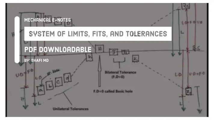
Types of Fits: Clearance Fit, Transition Fit, Interference Fit [PDF]

Fit is defined as the degree of freedom of tightness between the mating parts in an assembly process, it is also defined as the relationship between the hole and the shaft during the Assembly is called Fit. In this article, we are going to discuss different types of Fits in a detailed way.
The various parameters that can be included are Maximum Interference, Minimum Interference, Maximum Clearance, minimum clearance, etc.
Types of Fits:
The 3 types of fits are as follows...
- Clearance Fit
- Interference Fit
- Transition Fit
Go through this article till the end, so that you can understand different types of fits briefly.
Fit obtaining parts are either movable or fixed joints.
Example of a fit are, Shaft and Bearing assembly.
READ MORE
Type of Screw Driver- [By: The Unbox Factory]
Movable Joint:
The shaft running in a bearing can move in relation to it and thus forms a movable joint.
Fixed Joint:
Pulley mounted on the shaft forms a fixed joint.
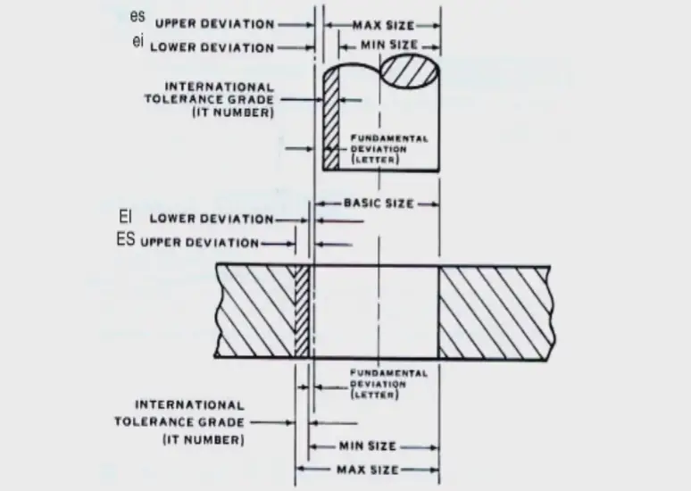
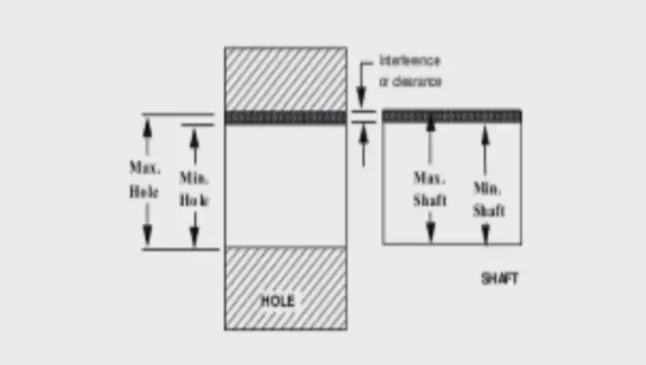
In this article, I will be defining all these parameters with respect to the hole and shaft assembly. Each Fit in this article is represented by a condition that needs to be satisfied and extreme cases are shown with respect to the assembly.
Clearance fit:
The dimensions of the hole and shaft are such that always clearance or gap is existing between hole and shaft called Clearance fit.
The condition of this type of fit is Hole size must be greater than Shaft size.
Extreme Cases:
- Lower Limit of Hole v/s Lower Limit of Shaft = Hole>Shaft= Clearance Fit
- Lower Limit of Hole v/s Upper Limit of Shaft= Hole>Shaft= Clearance Fit
- Upper Limit of Hole v/s Lower Limit of Shaft= Hole>Shaft= Clearance Fit
- Upper Limit of Hole v/s Upper Limit of Shaft = Hole>Shaft= Clearance Fit
As Hole size is greater than Shaft size, it is called as Clearance Fit.
It is used in all the mating assemblies.
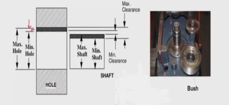
Maximum Clearance:
Maximum clearance is also called as worst-case clearance in the clearance fit.
Maximum Clearance = Higher limit of the hole - Lower limit of the shaft = Difference between minimum material limits.
Minimum Clearance:
Minimum Clearance= Lower limit of the hole - Higher limit of the shaft= Difference between maximum material limits.
Types of Clearance Fits:
The most commonly used fits of the clearance type are.
- Slide fit
- Running Fit
- Slack running Fits
- Easy Slide
- Loose Running Fits
Slide-Fit:
Slide fit has a very small clearance between two mating parts i.e. almost to zero
By this, we can say that the sliding fit is too closed to a transitions fit.
An example of a Slide fit is the tailstock spindle in a lathe machine.
Running Fit:
At moderate speeds, the running fit is employed in engineering for rotation of components. The clearance provides the required space for couplings.
For Example, couplings, Gears, etc.
Easy Slide Fit:
As the name implies, it provides a small clearance between the shaft and hole.
It is applicable for slow regular motion and non-regular motions
For Example, Piston.
Loose Running Fits:
As the name implies, Loose Running fits have the largest clearance and employed for rotation at high speeds of the components.
For Example, Plummer block, Idler Pulleys, etc.
Interference fit:
Dimensions of hole and shaft are such that without the interference of external agency the Assembly of hole and shaft is not possible.
The condition will be the shaft size must be greater than the Hole size.
External agency for assembly:
- Force/Pressure: that is by the application of force or pressure we can get the push-fit.
- Heating or Cooling: i.e. by the application of Heating or Cooling, we can get the shrink fit.
Extreme Cases:
- Lower Limit of Hole v/s Lower Limit of Shaft = Hole<Shaft= Interference is Required
- Lower Limit of Hole v/s Upper Limit of Shaft= Hole<Shaft= Interference is Required
- Upper Limit of Hole v/s Lower Limit of Shaft= Hole<Shaft= Interference is Required
- Upper Limit of Hole v/s Upper Limit of Shaft = Hole<Shaft= Interference is Required
According to the Transition Fit, in all the 4 cases interference is required. Let's look at the Interference fit.
It is used in non-mating assemblies like bearing bushes fitted into the bearing housing, key fitted into the keyway, etc.
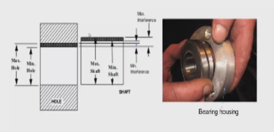
Maximum Interference:
Maximum Interference = Higher limit of the shaft - Lower limit of the hole= Difference between maximum material limits.
Minimum Interference:
Minimum Interference= Lower limit of the shaft - Higher limit of the hole= Difference between minimum material limits.
The power transmission capacity of interference fit is defined based on minimum interference only.
Types of Interference Fits:
Interference Fit is further Classified into the following types.
- Force Fit
- Tight Fit
- Shrink Fit
The explanation for the types of Interference fits are as follows.
Force Fit:
The force fits are employed for mating parts.
Example of a Force fit include Forging machine and the gears on the shaft of a concrete mixer.
Tight Fit:
Tight fits provide less interference than force fits.
Example of a Tight fit include Cylindrical grinding machine, stepped pulleys of a conveyor.
Shrink Fit:
There is negative allowance in Shrink fit and more amount of force is required for assembling the parts.
This is the explanation on Types of Interference Fits. Let's look at Transition Fit in a detailed way.
Transition Fit:
The dimensions of hole and shaft are such that sometimes the Clearance fit and sometimes the Interference fit is produced called Transition fit.
Condition:
According to the latest definition, if one of the components is lying in between higher and lower limits of the Other component produces transition fit.
Extreme Cases:
Case 1:
- Lower Limit of Hole v/s Lower Limit of Shaft= Hole>Shaft= Clearance Fit
- Lower Limit of Hole v/s Upper Limit of Shaft= Hole<Shaft = Interference Fit
- Upper Limit of Hole v/s Lower Limit of Shaft= Hole>Shaft = Clearance Fit
- Upper Limit of Hole v/s Upper Limit of Shaft= Hole>Shaft = Clearance Fit
Case 2:
- Lower Limit of Hole v/s Lower Limit of Shaft= Hole<Shaft= Interference Fit
- Lower Limit of Hole v/s Upper Limit of Shaft= Hole<Shaft= Interference Fit
- Upper Limit of Hole v/s Lower Limit of Shaft= Hole>Shaft= Clearance Fit
- Upper Limit of Hole v/s Upper Limit of Shaft= Hole<Shaft= Interference Fit
According to the above cases, the Transition fit sometimes produces Clearance Fit and Sometimes it is producing Interference Fit.
Types of Transition Fits:
The transition fit is classified into two types:
- Wringing Fit
- Push-fit
The explanation on Types of Transition Fits is as follows.
Wringing Fit:
In machines, where the parts can be replaced without any difficulty, there wringing fit is used.
Example of Wringing Fit include gears of machine tools.
Push-Fit:
It is charecterized by its clearance. An example of Push-fit is Gear Slip bushing.
It is used for producing non-mating assemblies like fit between Piston and Piston rings of IC engine, coupling, and coupling rings, etc.
Numerical on Limits, Fits, and Tolerance:
Problem: For a Shaft designated as 40 H8/f7, Calculate the tolerances?
Solution:
Given:
- Shaft designation = 40 H8/f7
- The above equation means that the basic size is 40 mm.
- I T 8-Tolerance grade for the hole is 8.
- I T 7-The tolerance grade for the shaft is 7.
As the basic size of 40 mm is lying in the diameter range of 30 to 50 mm, therefore,
The geometric mean diameter,
D = Square root of (50 x 30) = 38.73 mm
As we know,
Standard Tolerance Unit (i) = 0.45 x Cube root of (D) + 0.001 D= 0.45 × 3.38 + 0.03873 = 1.559 73 or 1.56 microns= 1.56 × 0.001 = 0.001 56 mm (1 micron = 0.001 mm)
The standard tolerance for the hole of grade 8 (IT8)= 25 i= 25 × 0.001 56 = 0.039 mm
The standard tolerance for the shaft of grade 7 (IT7)= 16 i= 16 × 0.001 56 = 0.025 mm
This is the complete explanation of all the 3 types of fits which are proved by the conditions and Extreme cases.
If you still have any doubts please feel free to mention in the comment section. And please don't forget to share this article on you your social handles.
FAQ's:
What is Fits?
What are the different types of fits?
More Resources:
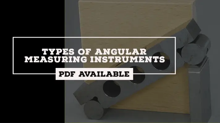
Types of Angular Measuring Instruments
Types of Steels
Types of dies
References:
- Engineering fit
- Manufacturing tolerances and fits - Nptel
Media Credits:
- All the Images: By Prof. Dr. Kanakuppi Sadashivappa, Department of Industrial and Production Engineering Bapuji Institute of Engineering and Technology-Davangere - NPTEL
- Feature Image: Modified by Author