Centrifugal Pump: Definition, Components, Working, Priming, Advantages, Disadvantages and Applications [PDF]
Centrifugal Pumps are most commonly used in industrial as well as Domestic applications for the transfer of fluids from one place to another place.Today, in this session, we are going to discuss components, working principle, priming, Advantages, Disadvantages, and Applications of the Centrifugal pump in a detailed way.
What is a Centrifugal Pump?
Centrifugal pump works on the principle of centrifugal force i.e. if a force is acting away from the center of the circle called a Centrifugal force. Similarly, as the lifting of the liquid is due to the centrifugal action, these pumps are called centrifugal pumps.
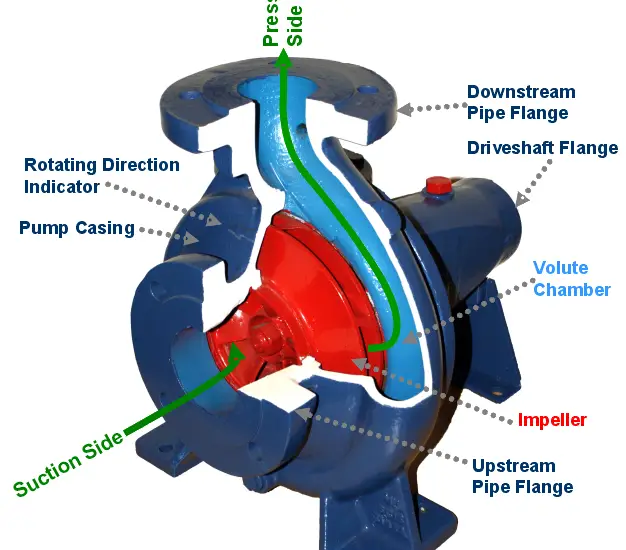
Components of the Centrifugal Pump:
The components of the Centrifugal Pump are as follows.
- Impeller
- Casing
- Suction Pipe and Delivery Pipe
- Eye of the Impeller
- Strainer or Foot Valve
- Driveshaft
Impeller:
It is a rotor(runner) with backward curved blades or vanes and is made to rotate at high speeds inside a spiral casing or Volute casing. It is a rotor used to increase the kinetic energy of the flow.
The impeller is coupled with Primemover such as internal combustion engine or electric motor which makes the impeller to rotate inside the Volute casing.
Impellers are divided into 3 types,
- Open Impeller
- Semi-closed Impeller
- Closed Impeller
#1 Open Impeller:
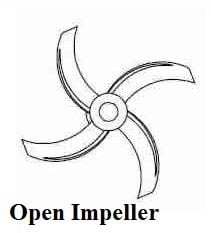
Open Impellers are used in smaller pumps which are easier to clean and repair.It has vanes that are attached to center hub and is directly mounted onto a shaft and there is no wall which can surrounds the vanes and that make the open impellers weaker than other impellers.
#2 Semi-Closed Impeller:
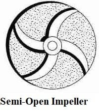
Semi-closed impellers find their applications in transporting the fluids which have a back wall that adds strength to the impeller but the other side is exposed to the interior of the pump housing. The efficiency in this semi-closed impeller is less compared to the closed impeller.
#3 Closed Impeller:
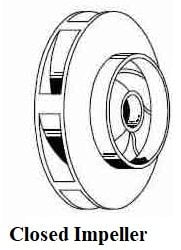
The Closed Impeller has a front and back wall around the vanes which can add and extra strength compared to Semi-closed impellers. The closed impellers are generally used in larger pumps where high-speed conditions are present.
Casing:
The casing is airtight as well as watertight. It’s cross-sectional area gradually increases towards the outlet of the pump.
Commonly three types of casing are used in a centrifugal pump,
- Volute Casing
- Vortex Casing
- Casing with Guide Blade
Volute Casing:
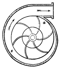
Volute Casing increases the cross-sectional area towards the outlet of the pump. The design design of volute casing causes the fluid pressure to increase towards the outlet of the pump.
Vortex Casing:
The circular chamber is provided between the casing and the impeller in the case of Vortex Casing. It is much more efficient than Volute casing.
Diffuser Casing:
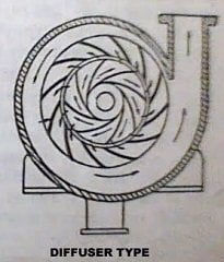
The purpose of the diffuser is to increase the efficiency of centrifugal pump by gradual expansion and less turbulent area for the liquid to flow in the pump.
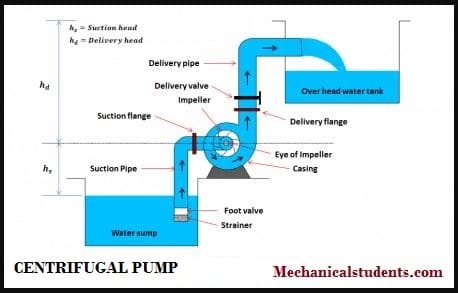
Suction Pipe and Delivery Pipe:
Water enters into the impeller from the suction pipe and delivers out from the delivery pipe.
Eye of the Impeller:
The upper end of the Section pipe is connected to the inlet of the pump or center of the impeller called as the eye of the Impeller.
The lower end of the suction pipe dips into a liquid in a suction tank or a sump from which the liquid is to be pumped or lifted up.
Strainer or Foot Valve:
The liquid first enters the strainer or foot valve provided in order to keep the debris(such as dust, waste particles, etc.) away from the pump and opens only in an upward direction.
The delivery pipe is connected to the outlet of the pump to deliver liquid to the required height with the help of a delivery valve.
Driveshaft:
The driveshaft is fixed at the centre of the pump such that it rotates in the same direction as the runner. Finally, from the driveshaft, electricity is generated.
Working of Centrifugal Pump:
The liquid enters into the impeller from suction pipe axially, at the eye of a pump and flows radially along with the blades, into the casing and then flow towards the discharge pipe.
Water/liquid enters the impeller with a negligible tangential component of velocity.
During the outward flow of water, the cross-sectional area of the casing increases such that the velocity should decrease and there should be an increase in the pressure head.
This can be easily understood by the continuity equation and Bernoulli’s equation.
As per the continuity equation,
A*V =Constant
Where
A-Cross-sectional area
V-Velocity.
As the cross-sectional area of the casing increases, there should be a decrease in the velocity of the liquid.
As the velocity of the fluid decreases, there should be an increase in Pressure head and this statement is supported by the Bernoulli’s equation.
As per Bernoulli’s equation,
Potential Energy(P.E.) + Kinetic Energy(K.E.)+Pressure Energy = Constant.
The Potential energy taken is to be zero at the eye of the impeller.
As Kinetic energy (K.E) =(1/2)mv2
As the cross-sectional area of the casing increases, there should be a decrease in the velocity of the liquid. The decrease in Velocity increases the Pressure head in the casing. In other words, the K.E. of the impeller is transformed into Pressure energy of water.
Priming in Centrifugal Pump:
Priming is the operation in which the suction pipe, casing of the pump and the portion of the delivery pipe up to the delivery valve are completely filled with the liquid which is to be pumped out so that all the air(gas or vapour) from this portion of the pump is driven out and no air pocket is left.
The necessity of priming is due to the fact that pressure generated in the impeller is directly proportional to the density of the fluid.
If the impeller runs in the presence of air, negligible pressure is generated because of the low density of air and hence no water will be lifted by the pump.
Hence, it is necessary to remove air from Suction pipe and casing. This is called as Priming.
During priming, it must be noted that the delivery valve is kept closed.
Even after filling the casing with water and ensuring the completion of priming, the delivery valve is not immediately opened.
Advantages of Centrifugal Pumps:
The advantages of Centrifugal pump are as follows.
- Small in size
- It accomadates less space
- Easy for maintenance
- Used for Industrial and domestic purpose also.
- less capital costs
- Can work from medium to low head of fluid.
Disadvantages of Centrifugal Pumps:
The disadvantages of Centrifugal pump are as follows.
- It cannot run with more viscous fluids like mud and waste.
- Priming is one of the disadvantage of Centrifugal pump.
- Due to priming, it produces cavitation.
- It leads to corrosion.
Application of Centrifugal Pumps:
- Industrial & Fire Protection Industry – boiler feed applications, Heating and ventilation, air conditioning, fire protection sprinkler systems, pressure boosting, etc.
- Oil & Energy – pumping crude oil, power generation plants
- Pharmaceutical, Food Industries, Chemical: sugar refining, food, and beverage production
- Agriculture, Waste Management & Manufacturing – Wastewater processing plants, drainage, gas processing, irrigation, municipal industry, and flood protection.
More Resources:
A.C. Mechanical Fuel Pump & S.U. Electrical Fuel Pump
Differential
References [External Links]: