Francis Turbine: Definition, Parts, Working, Velocity Diagram, Applications, Advantages & Disadvantages [PDF]

In the last session, we had discussed briefly on the Kaplan Turbine and Hydraulic Turbine. Whereas in today's session, we will be discussing on Francis Turbine along with it Definition, Parts, Working, Applications, Advantages & Disadvantages.
Lets see the definition of it...
Definition of Francis Turbine:
Francis Turbine is a mixed flow reaction Turbine in which water enters radially at its outer periphery and leaves axially at its centre. The Francis Turbine is the most commonly used Water turbine and was developed by James B Francis.
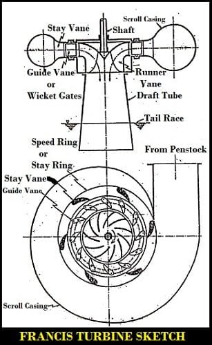
Francis Turbine Diagram:
The Diagram of Francis Turbine is shown below.
Parts of Francis Turbine:
The major Components or Parts of Francis Turbine are as follows.
- Scroll Casing (spiral casing)
- Speed ring (stay ring)
- Guide vanes
- Runner
- Draft tube
- Tailrace
The explanation for the parts of Francis Turbine are as follows.
Scroll Casing (Spiral Casing):
In Francis Turbine, Water from the Penstock enter a scroll casing (spiral casing) that surrounds the runner.
Speed ring (stay ring):
From the scroll casing, water passes through a speed ring or stay ring which consists of a series of fixed vanes called stay vanes.
The no. of stay vanes is usually taken as half the no. of guide vanes.
The function of the speed ring is to direct the water from casing to the guide vanes or wicket gates and further resist the load imposed upon it.
Guide Vanes:
From the speed ring, water passes through a series of guide vanes provided around the periphery (aerofoil shaped) of the runner.
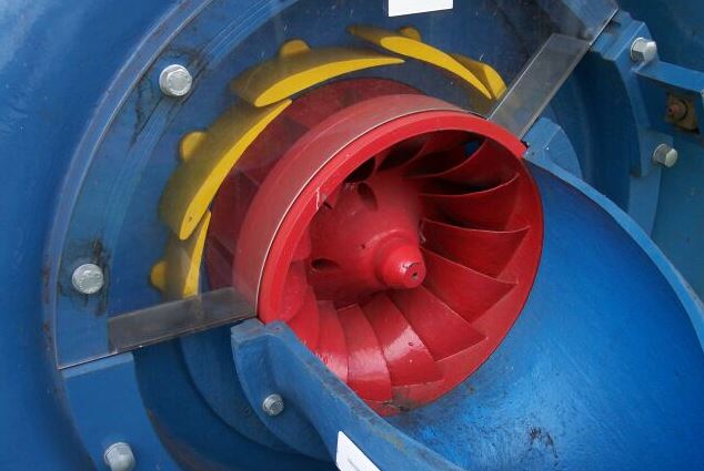
Their function is to regulate the quantity supplied to the runner and direct the water on to the runner at an angle appropriate to the design.
Runner:
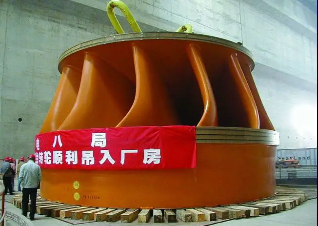
Francis Turbine blades are specially shaped that it has thin aerofoil cross-section, so when water flows over it, low pressure will be produced on one side and high pressure will be on another side. This will result in a lift force.
Draft tube:
A draft tube is a large pipe with an increasing cross-section area that connects the runner exit to the tailrace.
Tailrace:
The water after passing through the runner flows to the tailrace through a draft tube.
These are the components of Francis Turbine. Let's see the Working Principle of Francis Turbine in a detailed way.
Working Principle of Francis Turbine:
The Working Principle of Francis Turbine is as follows.
Water passes through various components of the Francis turbine to rotate the runner and generates electricity.
Firstly water enters into the penstock and surrounds the casing. The purpose of the casing is to provide an even distribution of water around the circumference of the runner, maintaining constant velocity for the water by gradually reducing the cross-sectional area of the casing.
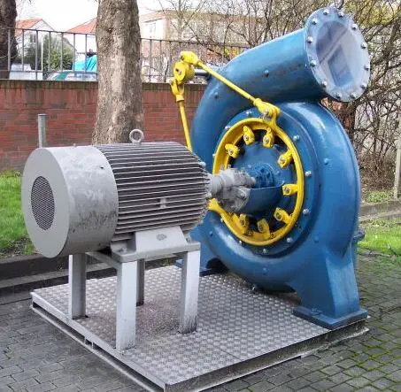
From the scroll casing, water passes through a stay ring which consists of a series of fixed vanes called stay vanes. From the stay ring, water passes through a series of guide vanes provided around the periphery of the runner.
The vanes are so shaped that water enters the runner radially at the outer periphery and leaves it axially at the inner periphery.
The most important part of Francis Turbine is the runner. It is fitted with a collection of complex-shaped blades. In runner, water enters radially and leaves axially. One more peculiar thing about the blade is it is having a bucket type of shape towards the outlet so water will hit and produce impulse force before leaving the runner.
Both Impulse force and lift force will make the runner rotate. So Francis Turbine is not a pure reaction turbine but a portion of force comes from the Impulse action also. Therefore, it is a combination of Impulse and Reaction forces and thereby Francis turbine is also called a Mixed Flow turbine.
From the Runner, water enters into the Draft tube which converts a large portion of velocity energy into useful pressure energy that is rejected from the runner.
Finally, water moves out through the Tailrace after passing from the draft tube. In this way, by the usage of Francis Turbine, electricity is generated.
Representation:
Scroll casing> speed ring>Guide vanes>Runner>Draft tube>Tail-race.
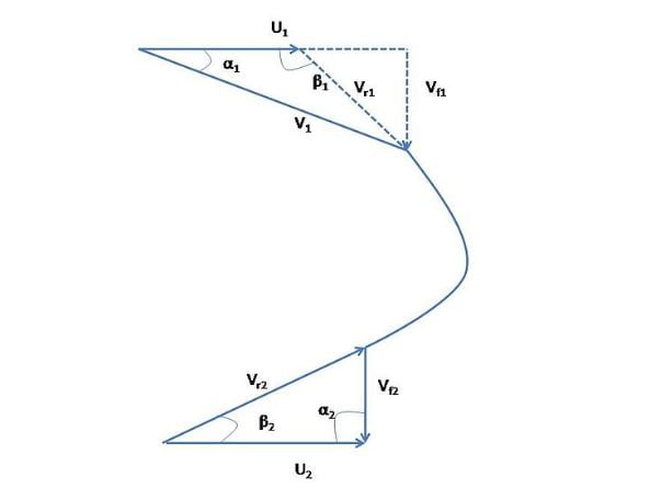
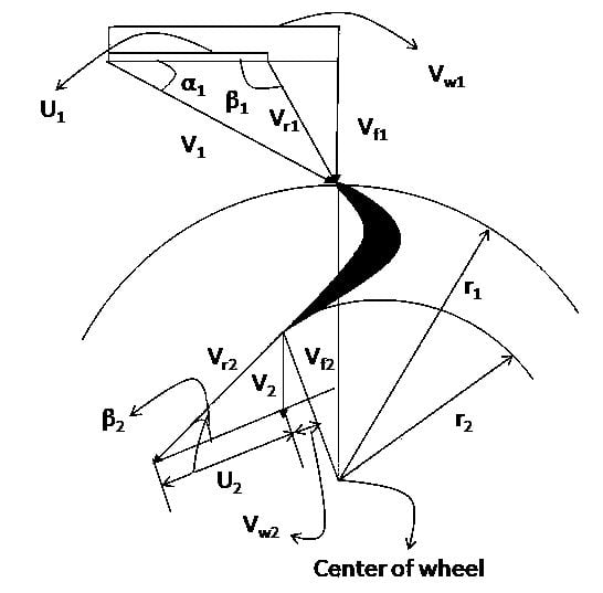
Francis Turbine Velocity Diagram:
The Velocity Diagram of Francis Turbine is shown below.
This velocity diagram clearly shows that in ideal cases, the whirl component of outlet velocity is zero i.e at the outlet the flow is entirely axial.
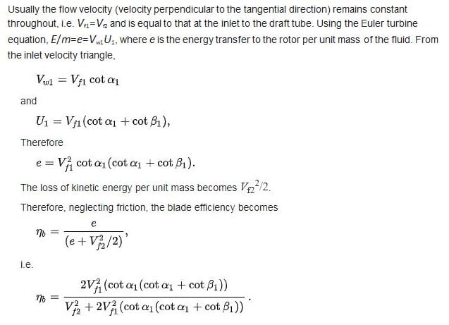
Blade Efficiency:
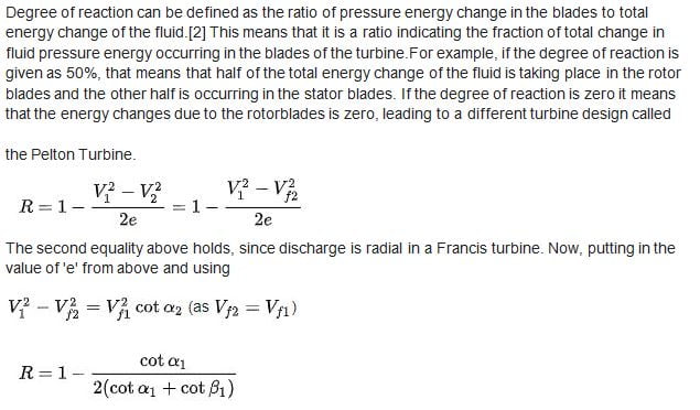
Degree of Reaction:
Applications of Francis Turbine:
The applications of Francis Turbine are as follows.
- It works over a wide range of head and flow rate
- One of the most efficient hydro-turbines
- Most widely used turbines to generate electricity
Advantages of Francis turbine:
The advantages of Francis Turbine are as follows.
- Its control is easy even with variable heads
- It has a small runner size
- Very little change in efficiency with time
Disadvantages of Francis Turbine:
The disdvantages of Francis Turbine are as follows.
- Inspection is relatively difficult
- Problem of cavitation
FAQs on Francis Turbine:
What kind of turbine is Francis turbine?
What is the hydraulic efficiency of the Francis turbine?
This is the detailed explanation of Francis Turbine. If you have any doubts, feel free to ask and we will reply you as soon as possible.
More Resources:
Kaplan Turbine
Pelton Wheel Turbine
References [External Links]:
- Hydraulic Turbines – an overview | ScienceDirect Topics
- HYDRAULIC TURBINES – Thermopedia


