Kaplan Turbine: Introduction, Definition, Components, Working, Application, Advantages & Disadvantages [PDF]
In the last session, we had discussed the Introduction to Hydraulic Turbines, Pelton Wheel Turbine, Centrifugal pump & Reciprocating pump in a detailed way. Therefore, in this article, we will discuss the Kaplan Turbine with its construction, working, advantages, disadvantages, and applications. So let's dive in.
Introduction of the Kaplan Turbine:
This Kaplan Turbine was developed in 1913 by Viktor Kaplan, an Austrian Professor. In his design, he combined automatically adjusted propeller blades and guided vanes to obtain efficiency over a wide range of water flow.
Since it is a reaction turbine, the reaction force of leaving the water is used to turn the runner of the Kaplan turbine.
As the water flows through the twisted blades, a lift force is generated in the opposite direction of the leaving water and that lift force causes the blades to rotate.
Definition of Kaplan Turbine:
Kaplan turbine is an axial flow reaction turbine which is suitable for low heads and hence requires a large quantity of water to develop a large amount of power.
It is more compact then Francis turbine which can run faster and maintains high efficiency. The Kaplan Turbine is located between the high-pressure water source and the low-pressure water exit.
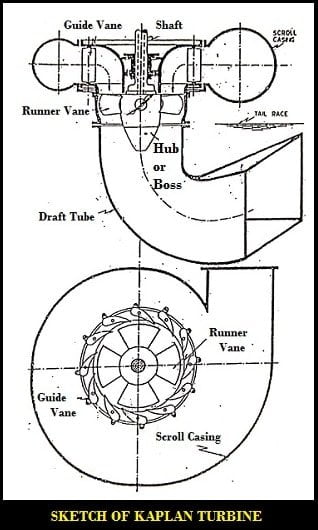
Components of the Kaplan Turbine:
The main components of a Kaplan turbine are:
- Scroll Casing
- Guide Vanes and Guide Mechanism
- Runner, Runner Blades, and Guide Vanes
- Draft Tube
The explanation of the above parts is as follows.
1. Scroll Casing:
The inlet is through the scroll casing which is in the form of a spiral. This ensures constant velocity of water flows along the path after entering into the casing.
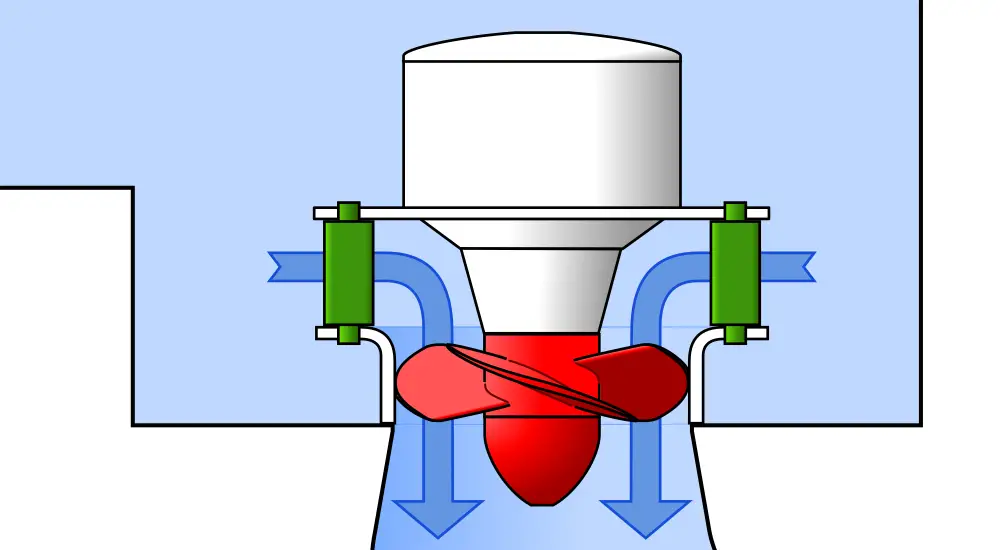
2. Guide Vanes and Guide Mechanism:
Water gets distributed by the guide vanes and can flow on to the runner blades in an axial direction. The blades are so shaped that water flows axially through the runner.
3. Runner, Runner Blades, and Guide Vanes:
The runner blades, as well as guide vanes, are adjustable while the turbine is in motion. Guide vanes are turned through a certain angle to regulate the flow. The axial flow of water acting on the runner vanes causes the runner to rotate.
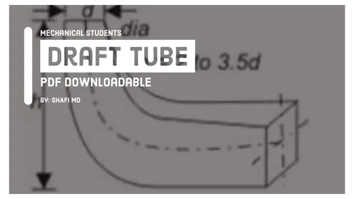
4. Draft Tube:
Finally, water is discharged to the tailrace through a gradually expanding tube called the Draught tube. A Kaplan Turbine runner has 4 to 6 blades.
When both the Guide vanes angle and the Runner blade angle may thus be varied, higher efficiency can be maintained over a wide range of operating conditions.
Working Principle of Kaplan Turbine:
The water from the penstock is to be allowed into the scroll casing of the Kaplan Turbine. The scroll casing is designed in such a way that the pressure flow is maintained.
The two types of blades which are used in this turbine are Guide Vanes and Runner blades.
The Guide vanes are fixed along with the spiral casing which makes the water to flow on to the runner whereas the runner blades are fixed to the Hub or Boss(runner) which rotates due to the reaction force of water hitting the blades of the runner.
The guide vanes are adjustable w.r.t the flow rate. The water takes a 90-degrees turn so that the direction of the water is axial to that of runner blades.
From the runner blades, the water enters into the draft tube where its pressure energy and kinetic energy decreases.
Kinetic energy is gets converted into pressure energy results in increased pressure of the water.
Due to the rotation of the runner, the shaft of the turbine rotates which thereby generates electricity.
Applications of Kaplan Turbine:
The applications of Kaplan Turbine are as follows.
- Kaplan turbines are widely used for electrical power production.
- It can work more efficiently at low heads and high flow rates.
- Its construction is very easy because of the smaller size.
- The efficiency of the Kaplan turbine is very high when compared to other hydraulic turbines.
Advantages of the Kaplan Turbine:
The advantages of Kaplan Turbine are as follows.
- Easy in construction
- The Kaplan turbine requires less space
- The efficiency of the Kaplan turbine is very high compared to others.
- At the lower head, this Kaplan turbine works much efficiently.
- The number of blades are less in this turbine.
Disadvantages of the Kaplan Turbine:
The disadvantages of Kaplan Turbine are as follows.
- The disadvantage of the Kaplan turbine is "cavitation", which occurs due to the pressure drop in the draft tube.
- The stainless steel as a material to the runner blades may reduce the problem of cavitation to some extent.
So this is the complete notes on the Kaplan turbine and its component, working principle, applications and advantages, disadvantages. I hope you are able to understand the lesson. If you have any doubts feel free to comment down below.
FAQ's:
Who developed Kaplan Turbine?
What is the difference between Kaplan and Francis turbine?
How many types of turbines are there?
More Resources:
Hydraulic Turbine
Pelton Wheel Turbine
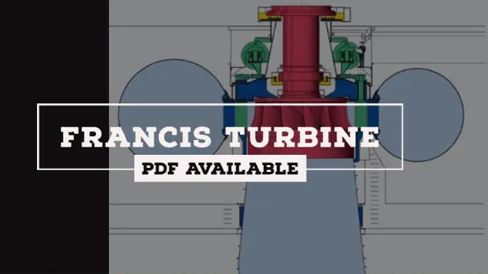
Francis Turbine
References [External Links]:
- Hydraulic Turbines - an overview | ScienceDirect Topics
- HYDRAULIC TURBINES - Thermopedia