A.C. Mechanical Fuel Pump & S.U. Electrical Fuel Pump: Parts and Working Principle [PDF]
Hey guys, in the last article, we had discussed the Fuel Supply system in S.I.Engine and in Today's article, we can discuss the Types of Fuel Pumps in S.I. Engines in a detailed way.
Note: Download Mechanical Fuel Pump PDF at the end of the article.
Types of Fuel Pumps Used in SI Engine:
There are two types of fuel pumps used in SI Engine, and those are:
- A.C.Mechanical Fuel Pump
- S.U.Electrical Fuel Pump
A.C. Mechanical Fuel Pump:
This is a diaphragm type of pump as shown in the figure. The diaphragm used is made out of a high-grade cotton impregnated with synthetic rubber.The valves are made up of bakelite which is being lighter and keeps the inertia stress minimum.
Components of A.C. Mechanical Fuel Pump:
The components of A.C. Mechanical Fuel Pump are:
- Eccentric or Cam
- Diaphragm
- Pull rod
- Strainer
- Inlet Valve
- Pressure Valve
- Outlet valve to Carburettor
Working of Mechanical Fuel Pump:
The drive for the pump is taken from the camshaft by means of an eccentric or cam. The eccentric operates the rocker arm which is in conjunction with the diaphragm return spring, which pushes the diaphragm up and down.
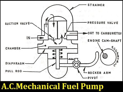
The downward movement of the diaphragm causes vacuum in in the chamber which causes the inlet valve to open and the fuel then goes through the strainer into the chamber.The next upward movement of the diaphragm causes the inlet valve to close while the outlet valve opens and the fuel goes out to the carburettor float chamber.
In this way, the pressure in the petrol pipeline between the fuel pump and the carburetor is kept under a pressure of 20 Kpa and 35 Kpa.
The exact pressure range is being determined by the stiffness of the diaphragm return spring. If the pressure is low, the petrol supply will not be able to keep pace with the demand under high speed or high load conditions. On the other hand, if the pressure is excessive, the needle valve of the carburetor float chamber may be forced open causing the flooding of the carburetor.
There is no need to pump more fuel when the float chamber of the carburetor is completely filled up. But if the engine continues to run at light load, the camshaft will be running all the time and if no other means are provided the pump will build excessive pressure which may damage the pump itself.
This is taken care of by the diaphragm return spring, which remains partially or fully compressed depending upon the line pressure even though the rocker arm continues to be moved up and down by the eccentric.
Thus the movement of the diaphragm gets restricted or even zero which decreases or even stops the supply of petrol from the float chamber from the pump until engine consumption uses some of the petrol in the carburetor float chamber.
For further surety against damage, the connection between the rocker arm and the pull rod is made flexible and when the float chamber is full, the diaphragm is not operated though the camshaft is running all the time.
S.U. Electrical Fuel Pump:
In this type also, the diaphragm is used. Alternate vacuum and pressure are produced due to the movement of the diaphragm which is caused electrically in this case.
Components of S.U. Electrical Fuel Pump:
S.U. Fuel pump is consists of following components:
- Diaphragm
- Breaker Point
- Power from the Ignition switch
- Solenoid
- Armature
Working of S.U. Electrical Fuel Pump:
Closing the ignition switch energizes the solenoid winding and the magnetic flux is created, which pulls the armature to which the diaphragm is attached. Thus the diaphragm moves to cause suction in the pump chamber and the fuel is drawn into the chamber.
But as soon as the armature moves, it interrupts the electric supply by disconnecting the breaker points, the solenoid is de-energized and the armature falls back causing the diaphragm to move so as to create the pressure in the pump chamber which opens the outlet valve and the fuel goes out to the carburetor float chamber.
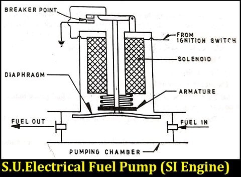
This movement of the armature, however, completes the circuit again and the solenoid again gets energized. The whole cycle is again repeated and the fuel continues to be pumped.
Electrical pumps need not be situated necessarily close to the engine, but they are mostly located near the fuel tank. Thus these are not subjected to engine heat.
Further, an electrical pump does not need to wait for the engine to start. It starts operating immediately as the ignition is switched on.
This is a detailed explanation of Mechanical Fuel Pump and Electrical Fuel Pump. If you have any doubts, feel free to ask from the comments section.
So this all about the S.U. Electrical Fuel Pump, and A.C. Mechanical Fuel Pump. If you have any doubts, feel free to comment down below, and don't forget to share this article on your favorite social channels
References:
- How a fuel pump works | How a Car Works
- (PDF) Fuel Pump (Hammad Hassan)
Media Credits:
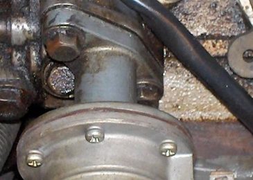
- Mechanical Fuel Pump: By Sonett72 at English Wikipedia - Transferred from en.wikipedia to Commons., Public Domain, https://commons.wikimedia.org/w/index.php?curid=1859997
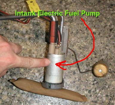
- Electrical Fuel Pump: By The original uploader was Mechanic at English Wikipedia. - Transferred from en.wikipedia to Commons., Copyrighted free use, https://commons.wikimedia.org/w/index.php?curid=1860028