Engineering Drawing Instruments and Their Usage [PDF]
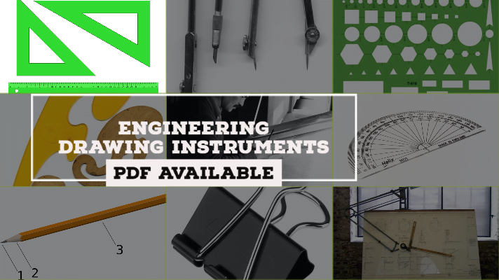
In this paper, I am going to familiarize you with the Engineering Drawing Instrument. So let's dive into the article.
Engineering Drawing Plays a crucial role in the life of Every Mechanical Engineering student because he has to bear that subject throughout his BTech. Apart from the Engineering Drawing, Production Drawing and Machine Drawing was also need to be learned by the Engineering student.
In Engineering Drawing, we have to draw and understand the largest buildings on a drawing sheet, not by reducing the dimensions but by reducing the scale. To measure any component, we need a set of Drawing Instruments in Engineering Drawing which are presented below.
Instruments Used in Engineering Drawing:
The instruments used in engineering drawing are:
- Drawing sheet
- Drawing board
- Mini drafter
- Eraser
- Pencils
- Protractor
- French curves
- Templates
- Paper Holders
- Set squares
- Compass
- Divider
The Detailed explanation of above mentioned Drawing Instruments are shown below.
1. Drawing Sheet:
Drawing sheet is a white paper on which an object is drawn which is available in various sizes as shown below.
| Drawing Sheet Type | Dimensions (Length X Width) (mm) |
|---|---|
| A0 | 841 X 1189 |
| A1 | 594 X 841 |
| A2 | 420 X 594 |
| A3 | 297 X 420 |
| A4 | 210 X 297 |
| A5 | 148 X 210 |
2. Drawing Board:
It is an object(table) on which the drawing sheet is placed. It is made up of wood and available in the rectangular cross-section. The drawing sheet is placed on the drawing board and is fixed by means of clips which are either plastic or metal materials.
The dimensions of the drawing board w.r.t length, width and thickness are presented below.
| Type of Drawing Board | Length X Width X Thickness (mm) |
|---|---|
| D0 | 1500 X 1000 X 25 |
| D1 | 1000 X 700 X 25 |
| D2 | 700 X 500 X 15 |
| D3 | 500 X 350 X 15 |
3. Mini Drafter:
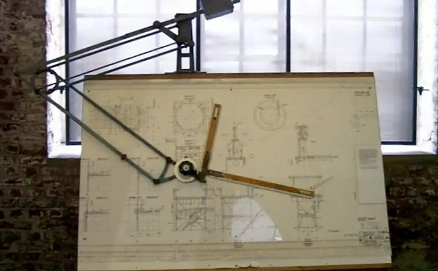
It is used for drawing vertical lines, horizontal lines, inclined lines, parallel lines, angles, perpendicular lines, etc. Mini Drafter generally consists of two scales that are perpendicular to each other and are calibrated in 'mm'. One end of the scale is to be connected to the edge of the table and the other end is used to mark and measure the dimensions.
5. Pencils:
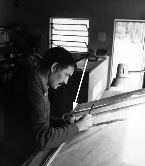
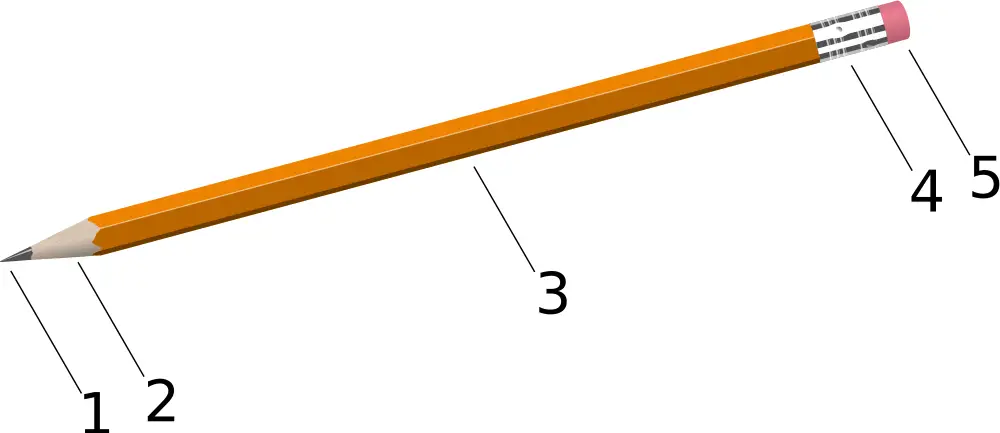
Pencils are the main drawing instruments used to draw the lines, circles, arcs, polygons, etc. w.r.t. the scale provided. Some of the pencils are hard and some of the pencils are smooth. The hard pencils are used to draw the construction lines and the smooth pencils are used to draw the main lines.
Depending on the smooth and hard quality or the hardness, pencils are classified into 18 grades and they are as follows.
| Grade of Pencil | Hardness of Pencil |
| 9H | Hardest |
| 6H, 5H, 4H | Extremely Hard |
| 3H | Very hard |
| 2H | Hard |
| H | Moderately hard |
| F | Firm |
| HB | Medium hard |
| B | Moderately soft and black |
| 2B | Soft and black |
| 3B | Very soft and black |
| 4B, 5B, 6B | Very soft and very black |
| 7B | Softest |
Out of the above 18 grades of pencils, the following grades are used in engineering drawings.
| Grade of Pencil | Used to Draw |
|---|---|
| 3H | Construction lines |
| 2H | Dimension lines, center lines, sectional lines, hidden lines |
| H | Object lines, lettering |
| HB | Dimensioning, boundary lines |
6. Protractor:
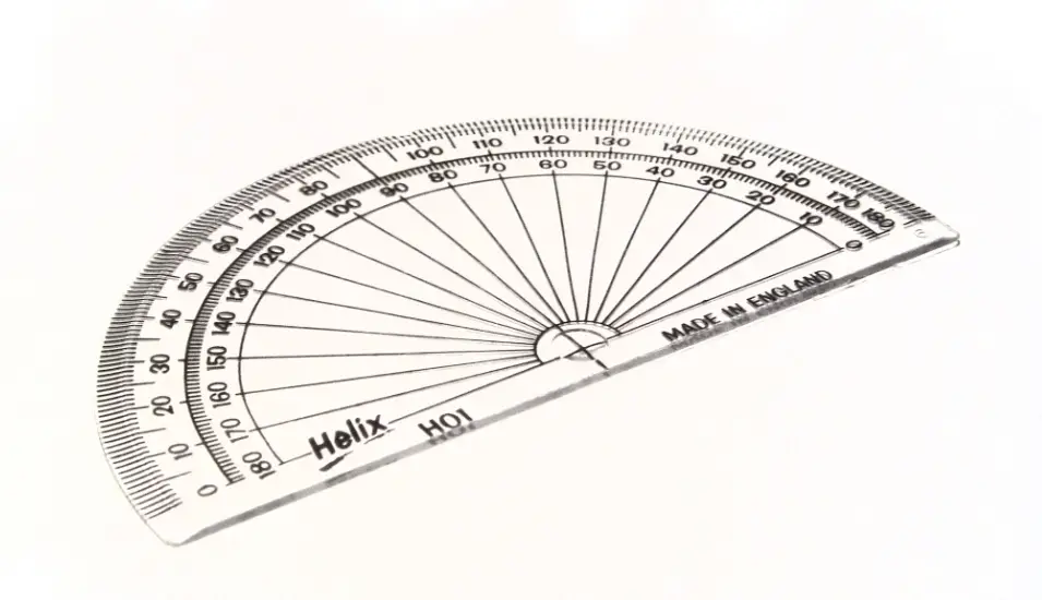
A protractor is used to mark the angle w.r.t. point or a line. It is in the shape of a semi-circle which is transparent and made of plastic. It can measure an angle from 0-180 degrees. The centre of this bottom line is marked with “O” or “C” from which the angles are measured.
7. French Curves:
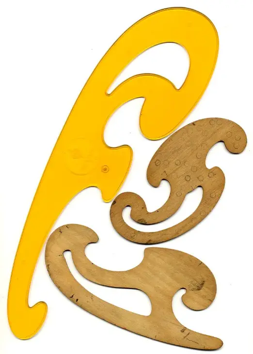
These are irregular in cross-section and were used to draw the small arcs and large splines which were not possible using a drafter. They are made up of plastic material.
8. Drawing Templates:
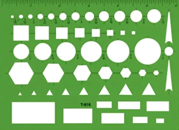
If you want to draw a circle of dia 4 mm, then it may not be possible with a compass. At that time, we need to use the templates. If you buy any geometry box for placing all the drawing instruments, then a drawing template was also given along with it which has Alphabets printed on it.
Similarly, in Engineering drawing, there are many things which cannot be drawn by the compass and that's the reason drawing templates were invented.
9. Paper Holders or Clips:
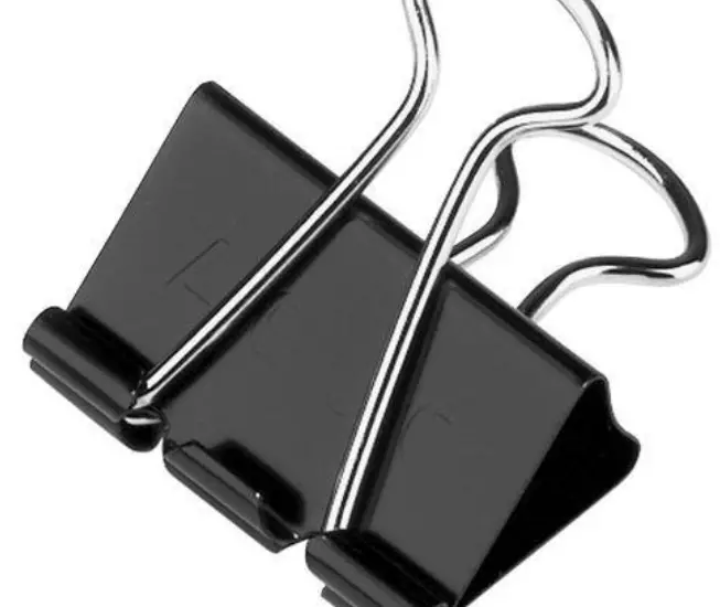
The clips are used to hold the drawing sheet on the drawing board properly. Generally, 4 clips are used for any drawing sheet.
10. Set Squares:
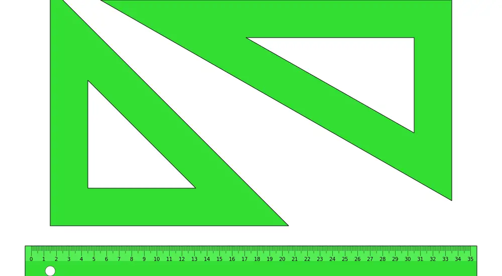
Set squares are used to draw lines with an angle between them. In most of the structures, 30, 45, 60 and 90-degree lines are most common.
Generally, set squares are of two types:
One is 45 degrees set square and another is 30 – 60 degree set square. Both are required in the drawing.
45 set square has a side of 25 cm while 30-60 set square has 25 cm length on one side.
11. Compass:
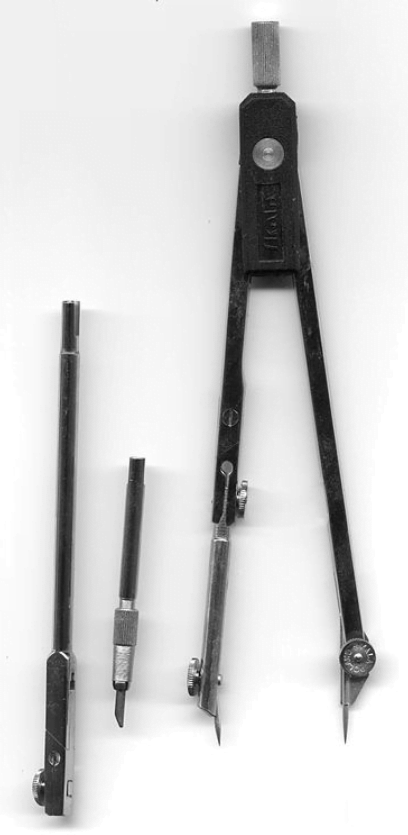
It is used to draw a line or a circle. It generally consists of two legs. One end has a sharp tip and the other end has a holder. The pencil is to be placed in that holder and is to be tightened using a screw.
This is the detailed explanation of Drawing Instruments which you need for Engineering Drawing. I hope this article is helpful to you. If you have any doubts then feel free to comment down below, and also do not forget to share this stuff with your friend.
Some FAQ on Engineering Drawing Instruments:
What are the instruments used in engineering drawing?
What is a mini drafter?
How many types of pencils are used in engineering drawing?
More Resources:
Types of Angular Measuring Instruments
Linear Measurements: Definition, Standards, Methods & Instruments
Types of Measuring Instruments and their Uses
References [External Links]:
- Design Handbook: Engineering Drawing and Sketching
- Engineering Drawing - The Carter Center
- 1st Year Engineering Drawing [Youtube]

