Notes on Limits Fits and Tolerances [PDF]
Before understanding the System of limits fits and tolerances ,you need to have basic knowledge of what is a limit and what is Tolerance?
However, I have explained in detail the Types of Fits. You can check it once.
In this article, we will discuss on Limits Fits and Tolerance along with their types, tolerance accumulation, Indian system of Limits Fits and Tolerance and 18 Grades of tolerances in detail.
What is Limit?
The variation permitted on the given dimension is called Limit.
What is Tolerance?
The total variation permitted on the given dimension is called Tolerance. Or It is defined as the difference between a Higher limit and a Lower limit.
Tolerance = Higher Limit - Lower Limit.
It is difficult to manufacture the components to the exact dimensions and is costly. Therefore, it is always recommended to permit the same amount of variation on the given dimension.
Types of Tolerance:
There are two types of Tolerance.
1.Unilateral Tolerances
2.Bilateral Tolerances
1.Unilateral Tolerances:
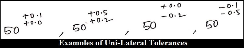
If the variation permitted is at only one side of the given dimension, called Unilateral Tolerance.
When the variation permitted is at only one side of the given dimension, then it is slightly difficult to manufacture the components. Hence the cost of manufacturing will be high.
Ex: Mating parts.
Even though it can be provided on mating and non-mating parts, because of the higher cost of manufacturing, it is preferable to provide only on the mating parts.
If the shaft is moving inside the hole is called a mating part else non-mating part.
2.Bi-Lateral Tolerances:
If the variation permitted is at both sides of the given dimension, called bilateral Tolerance.
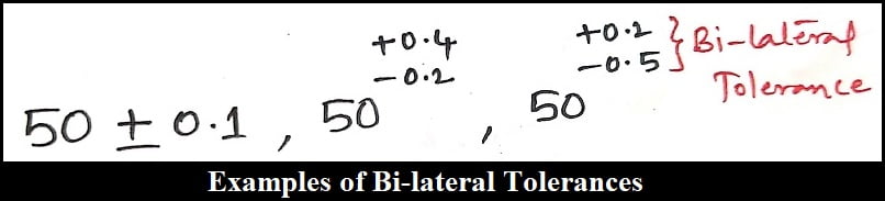
Because the variation is permitted on both sides of the given dimension, then the manufacturing of the components will be easier and the cost of manufacturing will be less.
Ex: Non-Mating parts.
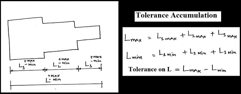
Tolerance Accumulation:
A component may have more than one dimension or the assembly may have more than one component. So that Total tolerance on the component or assembly is equal to the sum of the individual tolerances.
Let’s dive into the topic
System of Limits Fits and Tolerances:
The standard method of designating a hole shaft in the Assembly is called a system of limits, fits, and tolerances.
There are some standard definitions that you must know in the system of limits, fits, and tolerances.
Nominal size:
It is the size of the component decided based on the design considerations of a component.
Example: IC engines
Power(P) = 10 Kw @ 800 Rpm.
Basic Size:
It is the size based on which limits and tolerances of the component can be specified conveniently.
If the nominal size itself is taken as round off value, the basic size and nominal size will be taken as the same.
Deviation:
The amount by which, the limit of a component is deviating from the basic size called a deviation.
The deviation can be an Upper(Higher) deviation and a Lower deviation.
Upper Deviation or Higher Deviation:
The difference between the upper limit and the basic size of a component is called the upper deviation.
Lower Deviation:
The difference between the lower limit and the basic size of a component is called the lower deviation.
Fundamental Deviation:
It is the deviation, either upper or lower deviation which is a fixed and conveniently chosen deviation.
Hole Based System:
In the make-to-suit assembly, if the hole is made first approximately near to the required dimension and the shaft is made slowly such that it can be assembled into the hole according to the required assembly conditions is called Hole Based System.
According to the latest definition, if 'H' is used in the Assembly called Hole Based System.
Shaft Based System:
In the make suit assembly, If the shaft is made first approximately near to the required dimensions and the hole is enlarged slowly such that it can be assembled onto the shaft according to the required assembly conditions is called Shaft Based System.
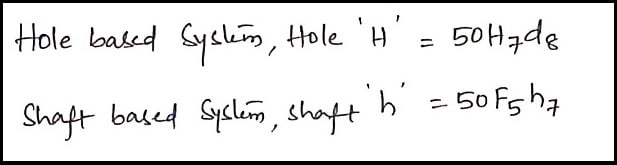
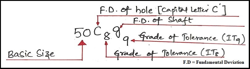
Hole Based System, Hole 'H' = 50H7d8
Shaft Based System, Shaft 'h' = 50F5h7
The priority of two systems:
Out of the two systems, the hole based system is the most commonly used one because reducing the diameter of the shaft slowly is easier when compared to enlarging the diameter of the hole slowly.
Indian System of Limits Fits and Tolerances:
Holes are specified by using Capital letters and the Shaft is specified by using Small letters.
There are 25 fundamental deviations, Shafts and holes will be used.
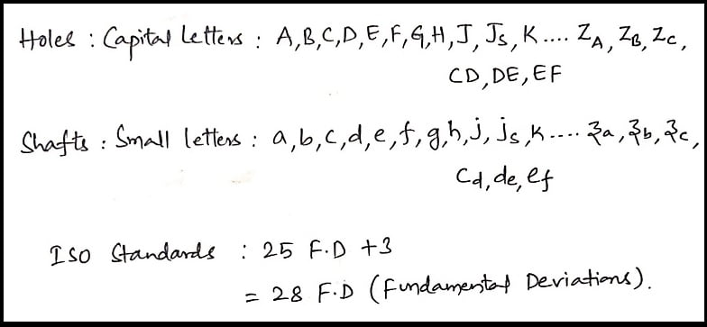
18 Grades of Tolerances:
IT01,IT0,IT1,IT2...IT16
The smallest is IT01
The largest is IT16.
Hole A = A01,A0,A1,A2…..A16.
Hole B = B01,B0,B1,B2…..B16.
Similarly,
Shaft 'e' = e01,e0,e1,e2…..e16.
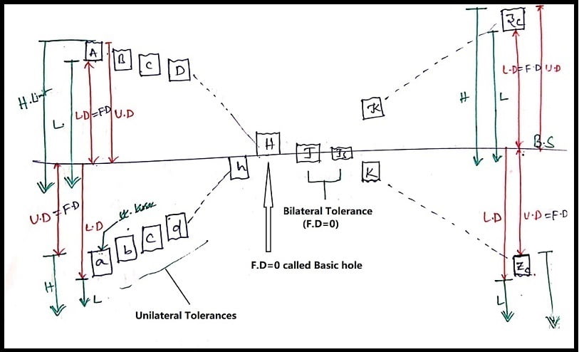
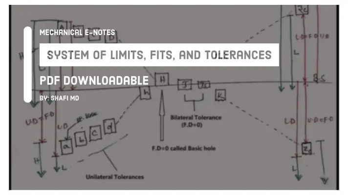
From the diagram, only J and Js are the Bilateral Tolerance of the components and all the other things are Unilateral Tolerance of the components.
The straight line indicates the corresponding limit of a component is fixed, irrespective of the grade of tolerance and the Variable line indicates that the corresponding limit is varying based on the grade of tolerance.
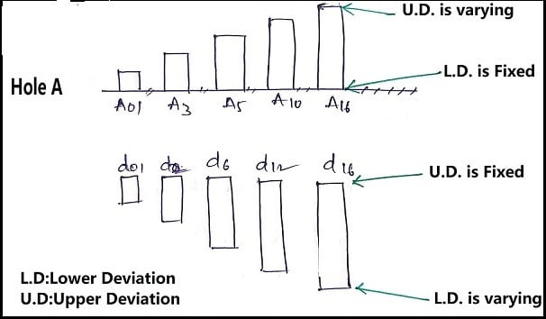
From the figure, holes A to H will have a Fundamental Deviation(F.D) = Lower Deviation(L.D) and for hole 'H', F.D. is equal to zero. (F.D.=0).
Therefore it is called a Basic hole.
Hence, If the basic hole is used in an assembly called a Hole Based System.
For hole J and Js, no F.D. and hole 'K to Zc', F.D = U.D.(Upper Deviation).
For shafts, a to h, F.D=U.D.
For shaft 'h' F.D =0.
Therefore, it is called a basic shaft and if the shaft is used in the Assembly called a Shaft Based System.
For shaft J & Js, no F.D. and shaft k to zc, F.D. = L.D.
For a given dimension, even though there are 450 varieties of holes are available, but because the Hole Based System is the most commonly used.
Only 18 varieties of hole 'H' will be used for producing assemblies with 450 varieties of shafts.
Note:
Hole H with shaft a to g → Clearance Fit
Hole H with shaft h to n → Transition Fit
Hole H with shaft p to z c → Interference Fit
Examples of Clearance:
Smaller Clearance: Piston and Cylinder of hydraulic press
Medium Clearance: Piston and Cylinder of I.C.Engine
Large Clearance: Shaft in Journal bearing.
Grades:
IT5 to IT10 → General Purpose
IT5 to IT10 → Very less important parts
IT5 to IT10 → Highly Important parts
IT5 to IT10 → Measuring Instruments
This is the detailed explanation for the System of Limits fits and Tolerance. If you have any doubts, feel free to ask and we will reply you in 24hrs.
More Resources
Iron-carbon Diagram Explanation
Cast iron properties
Q&A on Limits Fits and Tolerance:
What are the 3 types of tolerances?
What are different types of fits?
Clearance fit, Transition Fit and Interference fit.