
Sine Bar: Working Principle, Construction, Formula, Limitations & Viva Questions [PDF]
In the last session, we had discussed Marking and Measuring Tools used in Engineering Workshop. Apart from that, a detailed article on Working of Vernier Caliper was also discussed. But in today's article, we are going to study about Angular Measuring device called as Sine bar.
In this paper we are going to cover the topics like Working Principle, Construction, Limitations and other factors as well, so let's dive into the paper.
Working Principle of Sine bar:
A Sine bar is used to measure the angle of the given specimen accurately. It usually measures the angle of the specimen as well as locates the workpiece (specimen) properly to measure the angle of it.
The name Sine bar has come into the picture because the operation of the sine bar is completely based on Trigonometry.
i.e. Sin θ = Opposite/hypotenuse
Sin(θ) = h/L
where 'h' is the height of the slip gauges placed below the roller and 'L' is the length of Sine bar i.e. L=200 mm or 300 mm.
One end of the roller of the sine bar is placed on the ground and the slip gauges whose height needs to be constructed are to be placed below the other end of the roller.
To know the value of 'h', you need to know the value of 'θ' first and that can be solved by using Bevel Protractor.
Bevel Protractor measures the angle of the given specimen directly whereas Sine bar measures indirectly by the usage of Slip gauges.
First, the angle of the specimen is measured by the use of Bevel Protractor and from this, we need to calculate the value of 'h'.
Note: It is not possible to measure the angle of a given specimen directly employing a Sine bar. Instead of that, take the reference value of 'θ' and find the value of h.The construction of 'h' can be done employing Slipgauges.
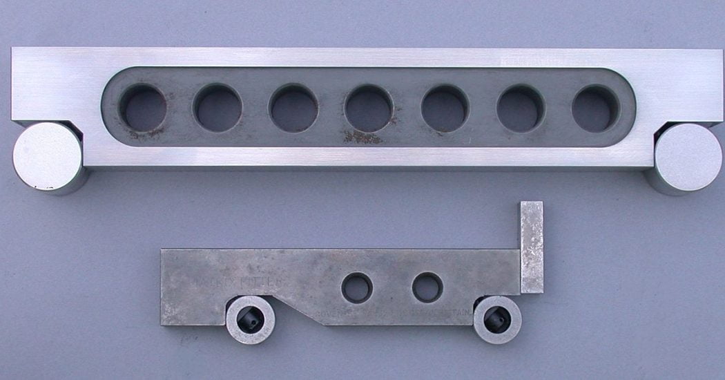
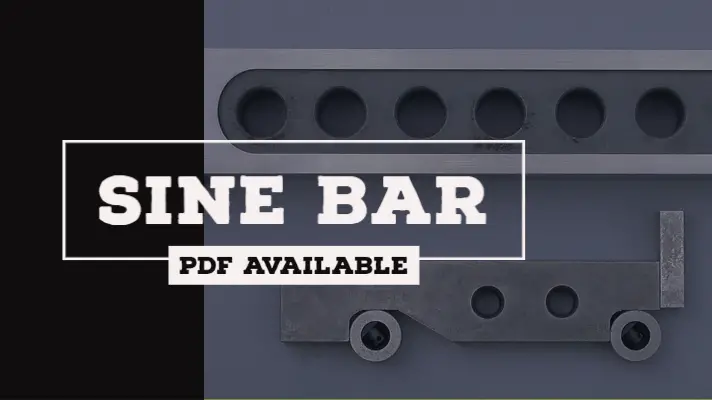
Construction of Sine Bar:
- The length of the sine bar is used for specifying a sine bar i.e. at 200mm,sine bar is nothing but the distance between the centers of the two rollers equal to 200 mm.
- The top and bottom surface of the sine bar must be parallel to the line joining to the center of the rollers.
- Holes are produced in the sine bar for reducing the weight of the sine bar so that handling of the sine bar will become easier.
- Only sine bar can't be used for measurement of angles of a component, but the sine bar is always used in association with slip gauges or Height Gauge for measurement of the angles.
The formula of Sine Bar:
The Formula for the sine bar is represented in terms of the height of the slip gauges constructed from the ground(h) and the length of the sine bar i.e. the distance between the centres of two rollers and was represented below.
Sin(θ) = h/L
Limitations of the Sine Bar:
- Any unknown projections present in the component will cause to induce errors in the angle measured.
- For the building of the slip gauges, there is no scientific approach available and it is to be built on the trial and error basis and it is a time-consuming process.
- During measurement of an angle by using sine bar, the length of the sine bar should be greater than or equal to a length of the component to be inspected.
Sin(θ) = h/L
- If the length of the component Inspected is very long then there is no sine bar available which is longer than the Component. In such cases, the sine bar will be used in association with Height Gauge for measurement of the angles.
Sin(θ) = (h2-h1)/L
Factors influencing the angle measured by using Sine Bar:
- An error present in the length of the sine bar (? L)
- The difference in Dia of the rollers (d1 not equal to d2).
- Error present in the building of slip gauges.
- Parallelism error between gauging surface and line joining to the center of the rollers.
The surface of the sine bar which is in contact with the component is called the gauging surface.
In general, sine bar is used for measurement of smaller angles only,but not for larger angles this is because of a small amount of error present in the sine bar which is causing to produce smaller amount of angular errors.
If it is used for measurement of smaller angles, the same small amount of error present in the sine bar is causing to produce a large amount of angular error during measurement of larger angles.
Sine bar Viva Questions:
1. What is the purpose of a sine bar?
Sine bar is used along with slip gauges for the precise angular measurement of any component.
2. Why there are holes in sine bar?
The holes are drilled into the body of sine bar to reduce the weight of it and also to facilitate easy handling.
3. Why is a sine bar not suitable for measuring angle above 45?
The sine bars become inaccurate as the angle exceeds 45° because the bar(product) is physically clumsy to hold at that position and even a slight error of the sine bar can cause large angular errors.
4. How is a sine bar specified?
For it,Read the construction of Sine bar.
5.What is the least count of slip gauge?
There is no possibility of Least count for slip gauges because they are represented in terms of 0.5mm,1.0 mm and so on up to the desired value.
This is all about today's topic that is Sine Bar, I hope you have successfully understood the topic if you still have any doubts, feel free to post in the comment section, I would love to answer those.
References:
- Engineering Metrology - Course - Swayam
- Engineering Metrology - IIT Kanpur
- Unit 3: Sine Bar – Manufacturing Processes 4-5 - Pressbooks