Fitting Workshop Tools: Holding, Measuring, Marking, Cutting, Finishing, Striking & Power Tools [PDF]
Fitting is the process of assembling various parts manufactured in the machine shop. The various types of tools used in the Fitting Workshop are as follows.
In the last class, we discussed the Electrical Engineering Workshop in a detailed way, and in today's class, we are going to discuss Engineering Fitting Workshop.
Tools used in Fitting Workshop :
The Tools Used in the Fitting workshop are as follows:
- Holding Tools
- Marking Tools
- Measuring Tools
- Cutting Tools
- Finishing Tools
- Striking Tools
The detailed explanation of above mentioned Fitting Workshop Tools are as follows.
Holding Tools used in Engineering Workshop:
Holding tools are also known as Work Holding devices in the Fitting workshop. They are used to hold all types of components between jaws(Fixed Jaw and Movable Jaw).
The Various Work holding devices are
- Workbench
- Bench Vice
- Pipe Vice
- Hand Vice
- Toolmakers Vice
The Explanation for the Work Holding Devices is as follows.
Work Bench:
- It is used to hold various components on its surface.
- It also gives support to a human while performing various operations.
Bench Vice:
- Bench Vice is a holding tool that is used to hold the specimen or the workpiece between the two jaws.
The Parts of Bench Vice are:
- Jaws
- Fixed Jaw
- Movable Jaw
- Body
- Handle
Parts of Bench Vice with Explanation:
Jaws:
The Jaws are used to hold the workpiece by rotating the handle. In that, one jaw is fixed and the other is movable.
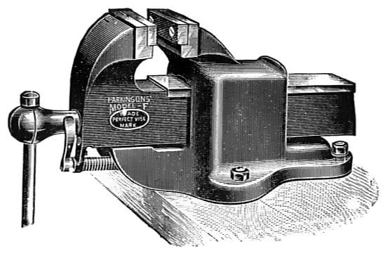
Body:
All the parts like a handle, jaws, etc. are connected to the body of a bench vice.
Handle:
If the handle is rotated in the CW direction, then the workpiece is fixed between two jaws.
If the handle is rotated in the CCW direction, then the workpiece is loosened from the jaws.
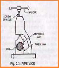
Pipe Vice:
- It is similar to Bench Vice but here the Circular/Cylindrical components are to be placed in between the upper and lower jaws due to the curvature of existing jaws.
- The Parts of the pipe vice are the handle, screw spindle, movable and fixed jaws, etc.
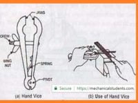
Hand vice:
- A hand vice is a tool that is designed to hold the workpieces in between the jaws.
- The wingnut is tightened in the CW direction to hold the w/p and loosened in the CCW direction.
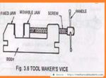
Tool maker’s vice:
- The screw-driven movable jaw for applying clamping force.
- Made from hardened alloy steel.
- Single piece construction with V-grooved Jaws.
- All surfaces including Jaws and Base are precision ground squares and
- parallel.
This is the explanation of Work Holding Devices in the Fitting Workshop. Let's go to the marking tools used in the fitting workshop.
Marking Tools used in Fitting Workshop:
Marking Tools are used to mark any dimensions on the surface of a workpiece. Marking Tools can vary w.r.t. the specimens used in the workshop and that you will see in the engineering workshop.
They are 3 types of Marking tools used in the fitting workshop and are as follows.
- Scriber
- Dot Punch
- Center Punch
The Explanation for the Marking tools is as follows.
Scriber:
- A scriber is a steel tool, used to scribe or mark lines on metal workpieces.
- It can be used in conjunction with a try square.
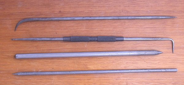
Dot Punch:
- It is used to specify the path of cutting.
- Firstly, the path is to be marked with a scriber, and then with the help of a dot punch, the path is hit by a hammer.
- For this purpose, the punch is ground to a conical point having 60 degrees included angle.
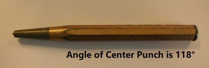
Center Punch:
- This is similar to the dot punch, except that it is ground to a conical point having 118 degrees included angle.
- It is used to mark the location of the holes to be drilled.
Measuring Tools used in Engineering Workshop:
Measuring Tools are used to measure any component w.r.t. the dimensions. Without these tools, it is not easy to measure the accurate values of the given .components.
Some of the Measuring Tools used in the Fitting Workshop are as follows.
- Steel rule & Measuring Tape
- Surface Plate
- Divider
- Try square
- Inside Calliper
- Odd leg caliper
- Outside Calliper
- Vernier Height Guage
- Micrometre
- Vernier Calliper
The detailed explanation of 10 Measuring Tools was HERE
Cutting Tools used in Fitting Workshop:
Cutting Tools are used to cut the given specimen(plate) w.r.t.the given dimensions. The material of the given specimen in the Fitting workshop is Mild Steel.
The Cutting Tools used in Engineering Workshop are
- Hacksaw (Cutting Tool)
- Files (Finishing Tool): Though it is a finishing tool, it comes under, cutting tools only.
Hacksaw:
A hacksaw is used for cutting rods, bars, pipes, etc. It consists of a frame, which is made of mild steel.
Depending upon the pitch of the teeth (Distance between the two consecutive teeth), blades are classified as:
- Coarse (8-14 teeth per Inch)
- Medium (16-20 teeth per inch)
- Fine (24-32 teeth per inch)
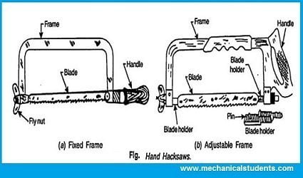
Hacksaw is classified into two types.
- Hacksaw with Fixed Frame
- Hacksaw with Movable Frame
In the above, hacksaws were different w.r.t.the frames only and the rest of the parts were the same. In the figure shown, one hacksaw has a fixed frame and the other has a movable frame.
Finishing Tools used in Fitting Workshop:
They are used to remove the material from the surface of the workpiece in order to get a high surface finish. The Finishing tools are also called Files.
Files are multi-point cutting tools. They are used to remove the material by rubbing on the metals(workpieces) to get a good surface finish.
Files are available in a number of sizes, shapes, and degrees of coarseness.
The various types of Files are as follows.
- Flat file
- Square file
- Triangular file
- Round file
- Half-round file
- Swiss or Needle file
The explanation of the above types of Files in the Engineering Workshop is as follows.
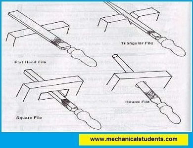
Flat File:
This file is used to remove the material from the rectangular cross-sections.
Square File:
This file is especially used to remove the material from the inside corners which are at right angles. As a flat file cannot able to work at those corners, thereby square file is used.
Triangular File:
This file can be used at inclined positions to make them linear.
Round File:
It is in the form of a circular cross-section which is used to remove the material from the circular components to get a good surface finish.
Half-Round File:
It is in the form of a semi-circle that is used to remove the material from the semi-circular cross-section components.
Swiss or Needle File:
It is in the form of a Needle which is used to remove the material from the Keyhole cross-section components.
Now Let's discuss methods of filing.
Methods of Filing:
There are two methods of filing.
- Cross Filing
- Draw Filing
The explanation of the Methods of filing is as follows.
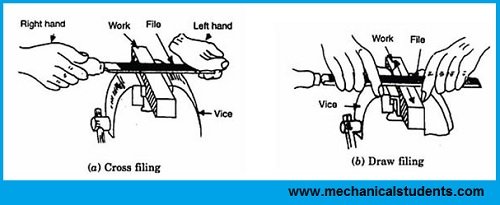
Cross Filing:
Filing in a direction perpendicular to the axis of a component is called Cross Filing. This filing method is used mostly in the Fitting Workshop.
Draw Filing:
Filing in a direction parallel to the axis of a component is called Draw Filing.
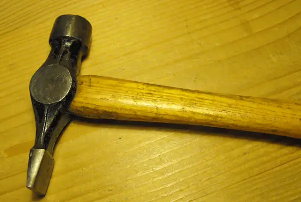
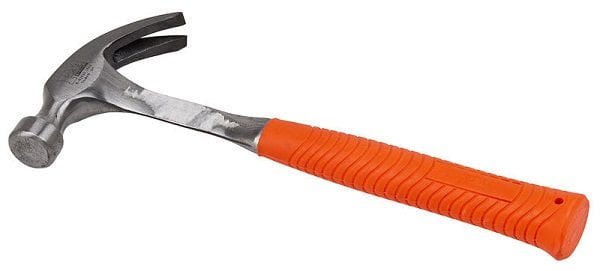
Striking Tools used in Engineering Workshop:
These tools are used to strike or hit the workpiece by the application of external force.
The Three Types of striking tools used in carpentry workshops are as follows.
- Cross-peen hammer
- Claw hammer
- Mallet
The explanations are as follows:
Cross-Peen Hammer:
- It has a cast Steel body and a wooden handle.
- The body has two parts. They are face and Peen.
- In a cross peen hammer, the peen is in the form of a narrow round edge used to remove the unwanted material from the workpiece.
Claw Hammer:
- It is used for striking as well as for pulling the nails from the wood.
- The claw face is used for pulling out the nails and the head face is used to drive the nails.
- It is made up of cast Steel.
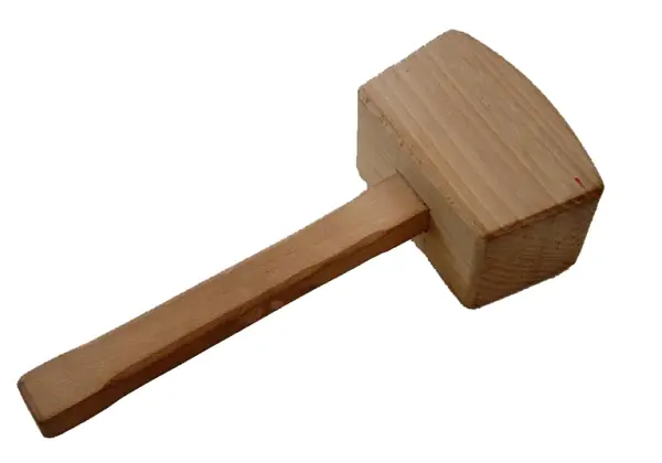
Mallet:
- It is used to strike the chisel on a wooden component.
- It is made up of hardwood and is round or rectangular.
These are the different Striking Tools used in Engineering Workshop.
These are the different types of Striking tools used in the Fitting Workshop. Let's see the operations, safe work practices, and Power Tools used in Engineering Workshop.
Operations used in Fitting Workshop:
A sequence of operations used in the Fitting Workshop is as follows.
- Filing (Rust from the workpiece)
- Measuring
- Marking
- Punching
- Sawing
- Filing (removing the unwanted portion)
Safe Work Practices in Fitting Workshop:
- Wear leather shoes and not sandals.
- Do not touch any electrical appliances.
- Don’t wear loose clothes in the workshop.
- Clean the unwanted material from the workbench before starting the operation.
Power Tools used in Workshop:
The tools which are driven by means of Power (Electric current) are called Power tools. In this article, I will be listing 4 Power tools used in the Fitting workshop.
- Power Hacksaw
- Circular Saw
- Drilling Machine
- Grinding Machine
The detailed explanation of the above power tools is as follows.
Power Hacksaw:
- A power hacksaw is a type of hacksaw that is powered by its own electric motor (also known as an electric hacksaw).
- Most power hacksaws are stationary machines but some portable models also exist.
- A Power Hacksaw is used to cut the metal at the required shape and size by means of a hacksaw which is driven by means of an Electric motor.
- The construction and working of Power Hacksaw were presented below.
- The forward stroke is the cutting stroke and the backward stroke is the idle stroke. In the backward stroke, the chips are removed from the workpiece.
- The workpiece is fixed between the two ends of the machine vice.
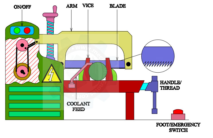
Components of Power Hacksaw:
The Power Hacksaw consists of the following parts.
- A Vertical column with Gears and Power buttons.
- Hacksaw
- Coolant
- Base
- Machine Vice
- Foot/Emergency Switch
Diagram of Power Hacksaw:
The Diagram of Power Hacksaw is shown below.
Working of Power Hacksaw:
When the power supply is given to the motor, the spindle attached to the motor rotates which is connected to the pulleys. The power is transmitted between the two pulleys by means of a belt.
One end of the link is connected with the pulley and the other end is connected to the fixed hacksaw frame which converts rotational motion into linear motion.
The position of the hacksaw on the workpiece is adjusted by means of a handwheel.
The linear motion of the hacksaw cuts the workpiece by means of a fixed blade having teeth in a forward direction.
The forward stroke is the cutting stroke and the backward stroke is the idle stroke. In this way, the hacksaw can cut the material which is fixed in the machine vice.
Circular Saw:
The circular saw is most commonly used for cutting wood, which may be used less optimally for cutting other materials with the exchange of specific blades.
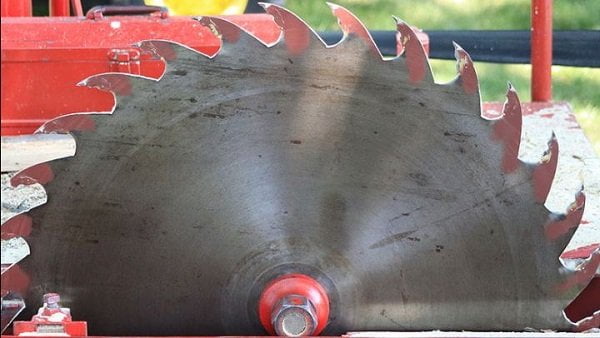
Basically, all circular saws consist of a motor with a circular blade fitted on a spindle. It can be carried from one place to another place for performing the operations.
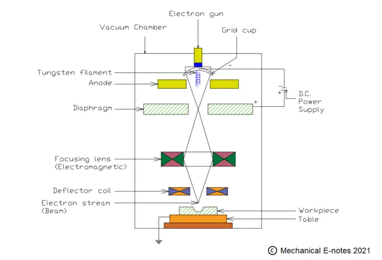
Drilling Machine:
Drilling Machine is used to drill holes on the components. The Angle of the drill bit used for removing the material from the surface of the workpiece is 118 degrees.
Grinding Machine:
A grinding machine is used to remove the material having (a low surface finish) from the surface of a workpiece by means of a Grinding wheel.
The Grinding wheel is a multi-point cutting tool that can have high MRR.
Here you can get detailed information on Surface Grinding Machine.
This is a detailed explanation of all the tools used in the Fitting Workshop. If you have any doubts, ask us and we will give a reply soon.
More Resources:
Classification of Machine Tools
Parts of Lathe Machine
References [External Links]:
- (PDF) What is Fitting Workshop Practice Presentation
- Fitting Shop Equipment - IITK