CNC Machine: Definition, Types, Components, Working, Function, Applications, Advantages, and Disadvantages [PDF]
In the last session, we had discussed NC Machine in detail whereas, in today's session, we will discuss on CNC Machine along with its Definition, Types, Components, Working, Function, Applications, Advantages, and Disadvantages. So let's start with the definition of CNC Machine.
Definition of CNC Machine:
If Every axis of a machine tool is controlled by using a mini-computer [which can run using Coding (G-Codes & M-Codes)] called as Computer Numerical Controlled Machine(CNC).
Types of CNC Machine:
The different types of CNC Machines are as follows.
- CNC Milling Machine
- CNC Laser Cutting
- CNC Plasma Cutting
- CNC Lathe Machine
- CNC EDM(Electric Discharge Machine)
- CNC Router
- 5-Axis Machine
- 3D Printer
- Pick and Place Machine
So let me explain one by one.
CNC Milling Machine:
Mostly the configuration of Milling machines is of 3 axes to 6 axes. In this machine, the components are to be machined with the help of Multi-point Milling Cutter.
I have already written about Conventional Milling Machine and you can check it too.
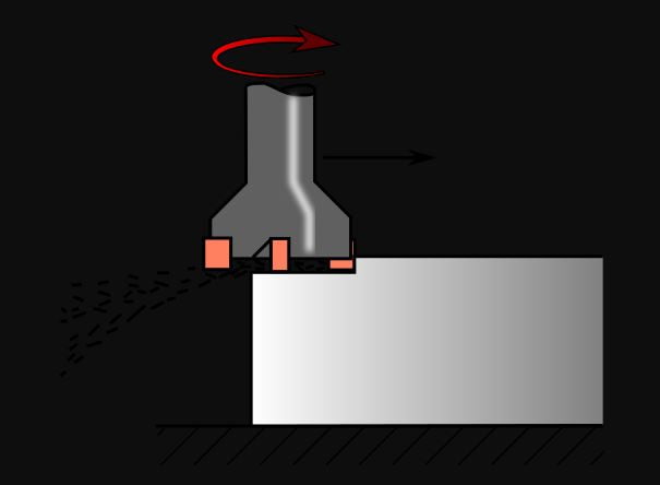
This machine is used to create holes, create bores, and also create slots in the workpiece and can also find its application in the creation of Spur gears.
As for the CNC Milling Machine is concerned, we need to create a part program in the form of G Codes and M Codes and it is inserted into the brain of CNC Machine. It can do its operation based on the work allocation in the program w.r.t. the coordinates.
The efficiency of the CNC Milling machine is very high compared to the conventional Milling Machine.
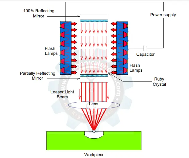
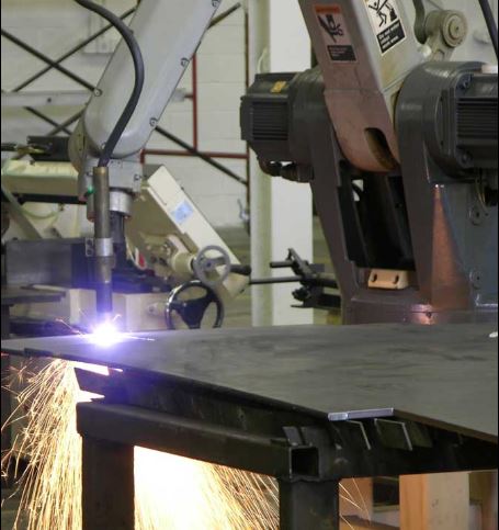
CNC Laser Cutting Machine:
As the name indicates that the cutting operation is carried out by means of laser called 'Laser Cutting'. If this operation is carried out on CNC called CNC Laser Cutting Machine.
The efficiency is very high compared to manual laser cutting.
It is generally used to cut the metal sheets.
They are designed to cut the tougher materials and it is similar to Plasma Cutting where instead of laser torch, the plasma torch is used to cut the materials.
Laser Cutting CNC Machines uses three types of Lasers. They are neodymium (Nd), CO2, or yttrium-aluminum-garnet (Nd: YAG).
CNC Plasma Cutting Machine:
Similar to CNC Laser cutting machines, Plasma Cutting machines are used to cut the materials.
They use a Plasma Torch to penetrate into the tougher materials which are not possible by laser cutting machines.
The temperature of the plasma is in excess of 20000 degrees Centigrade.
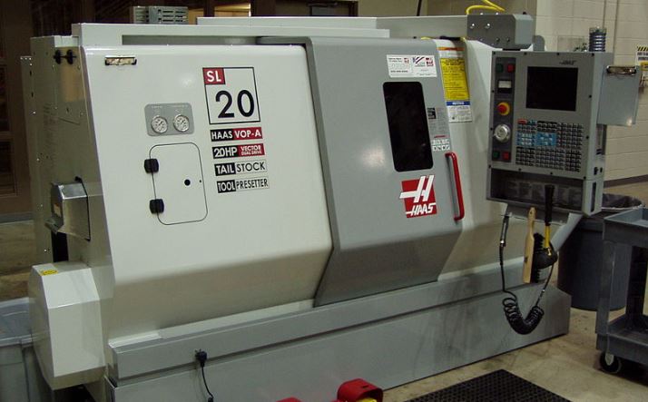
CNC Lathe Machine:
Before knowing about the CNC Lathe machine, you should aware of the parts and the working of Conventional Lathe Machine in detail so that you can understand the CNC Lathe machine effectively.
Lets know about CNC first...
CNC stands for Computer Numerical Control.
It is one of the machinery which was widely used in various industries for faster production of components.
Here, the program is generated by a team of engineers and that can be stored in the memory unit of the system.
There is no need to change the code once you added it to the machine unit for the repetitive purpose.
A semi-skilled operator is required to operate the working of lathe machine.
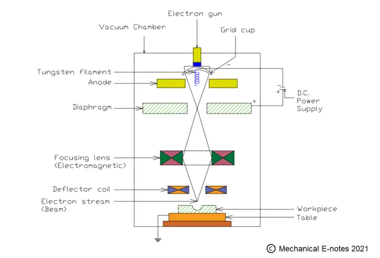
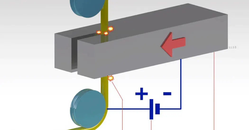
CNC EDM (Electrical Discharge Machine):
EDM stands for Electrical Discharge Machining which is used to cut the tougher materials and this EDM has the property of high MRR (Material Removal Rate).
Before knowing about CNC EDM, you should have the basic awareness of Conventional Electrical Discharge Machining such that you can understand the CNC EDM effectively.
CNC EDM is also known as the Spark CNC Machine that uses electrical sparks for removing the material from the surface of the workpiece.
The component is to be placed in between the work table which acts as anode and the tool electrode which acts as a cathode. Due to the excessive power, the dielectric fluid ionizes and the power is transmitted via the fluid to the workpiece and thereby material removal takes place.
As the entire operation can be carried out by means of a program in the CNC Machine, the components produced has a high surface finish compared to the traditional machines.
CNC Router:
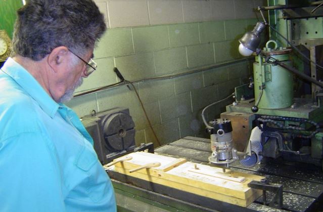
It is generally used for carpentry work i.e. making of interior and exterior decorations, musical instruments, furniture, etc.
It can works as per the sketch or design given to it in the form of program.
It executes high surface finish.
5-Axis Machine:
It is a machine that is capable of performing in 5-axes of the workpiece. It is generally used for making sculptures, larger turbines, etc.
Out of the 5-axes, 3 are translational axis i.e. X,Y and Z axis and the reast two axes are A and B which give the cutting tool a multidirectional approach.
3D Printing Machine:

As the name implies, additive manufacturing adds the material to create a 3D object.
3D Printing is also known as Additive Manufacturing in which the model of an object has to be created in any Modelling Software and has to save in the format of STL.
Pick and Place CNC Machine:
This type of CNC Machines is generally used in the construction of computers, tablets, cell phones, etc.
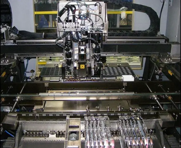
It consists of several nozzles that can pick up the electrical components and place them somewhere with respect to the need of the operator.
Similarly, it can does pick and place operation for other components too.
This is a detailed explanation of the different types of CNC Machines. Now let's discuss the components of the CNC machine in detail.
Components or Main Parts of CNC Machine:
A CNC Machine consists of following parts:
- MCU or CPU
- Drive Unit (Servomotor)
- Feedback Devices
- Mini Computer
- Very Few Manual Controls
Let me explain all these components.
MCU (Memory Controlled Unit):
MCU is working as a brain of human beings i.e. MCU is taking input information from the input devices, analyze the data, and all these decisions will be implemented by using output devices available in the CNC machine.
The Input Information is in the form of the decimal system and as the machine can understand only the Binary System of information, a device is required in MCU to convert the decimal to binary and vice versa, and that device are called as Arithmetic Logic Unit(ALU).
Drive Unit:
It is the device used for converting Electrical energy into Mechanical energy which is required for traveling the axis.
For example, Electric motor.
Here we can use Servo Motor as the drive unit in CNC Machining.
Servomotor:
It is also working similar to that of stepper motor but additionally, there is a quick action Braking System available in the motor so that whenever the power supply is getting stopped, the Braking System will be activated and stops all the moving parts.
Hence it is possible to get the high positional accuracy of the machine. Because the Servo Motors are not available at the time of development of the NC machine, the stepper motor can be used as a drive unit.
Feedback Devices:
It is a Displacement Measuring Equipment used to measure the actual distance traveled by the Axis and giving it as a feedback to the MCU and the MCU will compare the distance traveled by the axis with the distance to be traveled and determines the difference in distance.
The MCU will calculate the no.of pulses and send it to the drive unit. This process continues in the form of a cycle.
Feedback Device→MCU→Drive Unit.
Mini Computer:
Due to the usage of the minicomputer, the program will be fed into the machine through a keyboard and kept in the memory of a mini-computer in the form of a software program.
Due to the above program, the operation will perform without the intervention of the operator and the dimensional accuracy is also high.
Very Few Manual Controls:
Even though the above parts are present in the CNC machine, still the manual interventions are required for switching ON and OFF, loading and unloading of the workpiece, etc. called manual controls.
These are the CNC Machine Parts which are explained in a detailed manner.
Working of CNC Machine:
The working of the CNC Machine is based on mainly two software. Among that one is CAD (Computer-Aided Design) and the other is CAM (Computer Aided Manufacturing).
CAD software improves the quality of design and creates a separate database for manufacturing whereas CAM software involves programs that are written in the form of G Codes and M Codes.
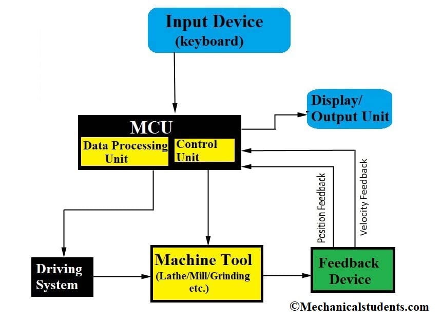
Steps for Working of CNC Machine:
The components of CNC machine which increases the efficiency are Input devices, Machine Control unit, Driving system, Machine tool (any machine like drilling, milling, etc.), and Feedback devices.
- The program was written with the help of G Codes and M Codes and was fed into the memory of the computer in the form of memory cards or floppy discs. Then the coordinates were given with the help of input devices like keyboard etc.
- After that, the data will be sent to the Machine Control Unit. As the CNC machine does not understand the numbers or numerals, the machine control unit converts it into the binary system.
- After Conversion, it will be sent to the Driving system for the motion of the components.
- Finally, the order will be given by the Machine Control Unit to the Machine Tool such that the work can be taken place.
- After the work was done by the Machine tool, it was inspected by the feedback devices and send that information to the Machine Control Unit.
- Then Machine Control unit calculates the work done by the machine tool to the actual work and calculates the difference.
- This difference will be fed up again to the Machine tool to do the rest of the operation.
- In this way, due to the presence of Feedback devices, the accuracy of the products produced will be high.
- Due to this high accuracy, the CNC machines will be used compared to Conventional machines for better production and time consumption.
Functions of CNC Machine:
The functions of CNC Machines are as follows.
- The function of CNC is to produce a component with high accuracy compared to conventional machines.
- Online editing (In-Process compensation) will be possible with the help of a program written in the CNC machine.
- It can store several part programs in bulk and can edit at any point in time.
- Increase in operating features and programming.
- Direct Numerical Control
Applications of CNC Machine:
The Applications of CNC Machines are as follows.
- The main application of the CNC Machine is its accuracy of metal removal compared to Conventional Machines like the Milling machine, Grinding machine, Drilling Machine, and Lathe Machine.
- It is used for prototyping many components in the industry.
- It is used for machining of Aluminium and Brass workpieces.
- It is used in various small scale and large scale industries.
- It is used for the production of Additive Manufacturing Materials.
Advantages of CNC Machine:
These are some advantages of CNC Machine:
- Due to Servo Motors as drive units, the positional accuracy of the component produced is better.
- Feeding the program into the machine through the keyboard is very easier.
- Duplication of software program will be easier i.e.the software program can be copied into the floppy or Disks and can Copy into any number of Machines.
- Because of the software program, the life of a program is infinity.
- Design modifications can be easily incorporated into the existing program.
- Because of very few manual controls, complete automation of the CNC machine is possible.
Disadvantages of CNC Machine:
The Disadvantages of CNC Machine are as follows.
- The cost of CNC Machine is very high compared to conventional machines.
- Lot of unemployment takes place due to the presence of CNC machine i.e. there is a reduction in labor and thereby there is no need of man power.
- Skilled operator is required to manage the work on the CNC which was fed up by the program written in the form of G-Codes and M-codes by engineers.
G Codes and M Codes of CNC Machine:
Before knowing about the G Codes and M Codes, we need to know about Part Programming.
Part Programming is not a language programming but it is a coded programming method used for writing the programs for the manufacturing of given components.
Part Programming uses standard codes and code means the name given for the program written for a standard measurement of the tool. These codes are used in part programming.
G-Codes Stands for General Purpose Codes and M-codes Stands for Miscellaneous or Machine Codes. A minimum of 2 marks will come from this region.
So let's start with G Code first!
- G 00: Rapid Traverse. G00 Code stands for Rapid Traverse. It means that whenever the tool required to travel ideally without removing any material. It is required to travel at maximum possible speed, in such cases G00 Code will be used.
- G 01: Linear Interpolation. Whenever the tool required to travel in a straight-line path, G 01 Code will be used.
- G 02: Circular Interpolation (Clockwise)
- G 03: Circular Interpolation (Counter Clockwise). Whenever the tool is required in a contour path, G 02 or G 03 will be used.
- G 04: Dwell. Dwell indicates temporary stoppage of a tool in the machine for a specified duration.
- G 05: Hold. Hold indicates stoppage of a tool in the machine for Unlimited Duration. For example, G04 F120 Here F120 indicates temporary stoppage duration in seconds.
- G 08: Acceleration. Whenever the machine is getting started, it has to start at the lowest velocity and reaches to the maximum velocity in a specified duration. For this, the G 08 Code will be used.
- G 09: Retardation. Whenever the tool is nearing to the destination, it has to reduce its velocity so that it is possible to stop the tool exactly whenever it is required. For this G 09 Code will be used. G 08 and G 09 are the Default codes used in part programming.
- G 17: Movement of Tool in XY Plane
- G 18: Movement of Tool in YZ Plane
- G 19: Movement of Tool in ZX Plane
- G 33: Thread Cutting with Constant Pitch.
- G 34: Thread Cutting with Increasing Pitch.
- G 35: Thread Cutting with Decreasing Pitch.
- G 41: Tool Radius Compensation Left
- G 42: Tool Radius Compensation Right
- G 70: English Programming (Inches)
- G 71: Metric Programming (mm)
- G 90: Absolute Mode. If each and every movement of the tool is indicated with reference to the only one single reference point called a machine reference point named as Absolute mode of Programming.
- G 91: Incremental Mode. If the Present position of the tool is taken as a reference point for programming the next position of the tool called as Incremental mode of programming. These are the 20 G-Codes of CNC Part Programming.
Note: Even though the incremental mode of programming is easy to write and modify but according to Indian conditions, we prefer to use the absolute mode of programming only because during the running of the program for producing the components, if the power failure occurs, after restoring the power, it is very easy to identify where the program has got stopped if it is an absolute mode of the program.
The remaining G-Codes required in Part Programming are as follows:
- G 06: Spline interpolation
- G 07: Hypothetical axis interpolation
- G 11: Mirror image cancel
- G 12: Mirror X-Axis values
- G 13: Mirror Y-Axis values
- G 14: Mirror XY Axis values
- G 20: Inch input (equivalent to G70)
- G 21: Metric input (equivalent to G71 )
- G 28: Return to machine coordinate origin
- G 29: Return from machine coordinate origin
- G 43: Tool length compensation +
- G 44: Tool length compensation -
- G 49: Tool length compensation cancel
- G 50: Scaling cancel
- G 51: Scaling
- G 53: Machine coordinate system selected
- G 54: Work coordinate frame 1 selection
- G 55: Work coordinate frame 2 selection
- G 56: Work coordinate frame 3 selection
- G 57: Work coordinate frame 4 selection
- G 58: Work coordinate frame 5 selection
- G 59: Work coordinate frame 6 selection
- G 61: Exact stop mode (block by block)
- G 64: Continuous mode (look-ahead)
- G 73: Peck drilling cycle
- G 74: Counter tapping cycle
- G 76: Fine boring cycle
- G 80: Canned cycle cancel
- G 81: Drilling cycle, spot boring
- G 82: Drilling cycle, counterboring
- G 83: Peck drilling cycle
- G 84: Tapping cycle
- G 85: Boring cycle
- G 86: Boring cycle
- G 87: Back boring cycle
- G 88: Boring cycle
- G 89: Boring cycle
- G 92: Work coordinates change
- G 93: Inverse time feed
- G 94: Feed rate per minute
- G 95: Feed rate per revolution
- G 98: Canned cycle initial level return
- G 99: Canned cycle R point level return
Now let see some important M Code too,
M codes play a vital role in the CNC Part Programming. Majorly M codes are used to write the main programs and Sub-Programmes in CNC Part Programming. Along with these M Codes, I will be writing about the Main Programmes and Subprograms which are used in CNC Part Programming.
However, 100 M codes are starting from (M00 to M99). But only 14 M codes that are important for the GATE point of View are presented below.
- M 00: Program Stop= G05
- M 01: Planned Stop= G04, for example, G 04 F & M 01 F. In both cases, the Stoppage duration was in secs.
- M 02: End of Main Program written without the use of Subprogram.
- M 30: End of Main Program written with the use of Subprogram.
- M 17: End of Sub Program.
- M 03: Spindle Start (Clockwise), for example, M 03 S 500. Where S 500 represents the rpm of the spindle.
- M 04: Spindle Start (Counter Clockwise)
- M 05: Spindle Stop.
- M O6: Tool Change, for example, M 06 T 13. Here T 13 Represents that the Existing Tool is replaced by T 13 and T can be up to T 32.
- M 07: Coolant Pump No.1 ON
- M 08: Coolant Pump No.2 ON
- M 09: Coolant Pump No.1&2 OFF
- M 10: Clamping (Tightening Chuck)
- M 11: De Clamp (Releasing Chuck)
- M 12: Clamp/Misc. on
- M 13: Clamp/Misc. off
- M 19: Oriented spindle stop
- M 47: Return to program start
- M 48: Bypass feed rate override cancel
- M 49: Bypass feed rate override
- M 90: User-defined DOS call 1
- M 91: User-defined DOS call 2
- M 92: User-defined DOS call 3
- M 93: User-defined DOS call 4
- M 94: User-defined DOS call 5
- M 95: User-defined DOS call 6
- M 98: Call sub-program
- M 99: Return from sub-program
So this is my complete explanation regarding CNC Machine Tool, I hope you liked this article, if you have any doubts feel free to post in the comment section, I will get back to you within 24hrs.
FAQs:
What is the M code in CNC?
What is the function of G Code?
What is CNC machine?
Why are CNC machines used?
Who is father of CNC machine?
More Resources:
NC Machine
Drilling Machine
Grinding Machine
Lathe Machine
References [External Links]:
- (PDF) Study on computer numerical control (CNC) machines
- Fundamentals of CNC Machining - TITANS of CNC Academy
- M Code and G Code of CNC Machine